Gear cutting machines with cone guitar. Circular Bevel Wheel Cutting Machines
Chapter 2
CUTTING CYLINDRICAL WHEELS WITH WORM MILLS
BASIC PROCESS INFORMATION
The cutting of teeth with a hob cutter is carried out on gear hobbing machines by the rolling method. The profile of the cutting part of the worm cutter in its axial section is close to the profile of the rack, therefore, the cutting of teeth with a worm cutter can be represented as the engagement of the rack with a gear wheel.
The working stroke (cutting movement) is carried out by rotating the cutter 4 (Fig. 1). To ensure running-in, the rotation of the cutter and the workpiece 3 must be coordinated in the same way as when the worm 1 and wheel 2 are engaged, that is, the speed of rotation of the table with the workpiece must be less than the speed of rotation of the cutter as many times as the number of teeth to be cut is greater than the number of starts cutters (with a single-pass cutter, the table with the workpiece rotates g times slower than the cutter).
The feed movement is carried out by moving the support with the cutter relative to the cut wheel (parallel to its axis). Radial feed (infeed) is also available in newer machine designs. When cutting helical wheels, additional
1. The main kinematic chains of gear hobbing machines
| Chain | What is provided | End elements of the chain | Movements to be linked | Setting body |
| Expressway | Cutting speed u, m / min (frequency of rotation of the cutter n, rpm) | Electric motor - milling spindle | Rotation of the motor shaft ( ne, rpm) and cutters ( n, rpm) | Guitar Speeds |
| Axial (vertical) feed chain | Innings Soi mm / rev | Table - caliper feed screw | One turn of the workpiece - axial movement of the support by Eo | Guitar pitch |
| Fission chain | Number of teeth to be cut z | Table - milling spindle | One turn of the cutter k / z table revolutions | Guitar division |
| Differential chain | The angle of inclination of the cut teeth in | Table - caliper feed screw | Moving the caliper to the axial step ta- additional rotation of the workpiece | Differential Guitar |
Rice. 1. The principle of operation of gear hobbing machines:
1 - worm; 2 - dividing worm wheel; 3 - blank; 4 - cutter; 5 - guitar division
rotation of the table with the workpiece associated with the movement of the feed. Therefore, the hobbing machine has kinematic chains and their tuning organs (guitars), indicated in table. one.
GEAR MILLING MACHINES
Construction and technical characteristics of machines
Depending on the position of the workpiece axis, gear hobbing machines (Table 2-4) are divided into vertical and horizontal, Vertical gear hobbing machines (Fig. 2) are made of two types: with a feed table and with a feed column (rack).

Rice. 2. General form vertical gear hobbing machine:
1 - table; 2 - bed; 3 - control panel; 4 - column; 5 - milling support; 6 - bracket; 7 - supporting rack
The machine with a feed table, on which the workpiece is fixed, has a stationary column with a milling carriage and a rear support stand with or without a cross member. The approach of the cutter and the workpiece is carried out by horizontal movement of the table (along the guides).
The machine with a feed column, which moves to approach the workpiece, fixed on a stationary table, can be performed with or without a rear rack. This is usually done on large machines.


Notes:
1. Machine tools with the letter "P" in the designation, as well as models 5363, 5365, 5371, 5373, 531ОА are machines of increased and high accuracy and are intended, in particular, for cutting turbine gears.
2. Large machines (mod. 5342, etc.) have a unit division mechanism for working with disk and finger cutters using the supplied overhead heads: for cutting wheels with external teeth using a finger cutter (see Table 5), wheels with internal teeth with a disk or finger cutter or a special hob cutter (see Table 1). On request, a broaching support for cutting worm wheels with tangential feed and a mechanism for cutting wheels with a taper angle of the tips of the teeth up to 10 °, a reversing mechanism for cutting chevron wheels with a finger mill without a groove are supplied.
3. Machine tools mod. 542, 543, 544, 546 and machines created on their basis are designed for cutting large worm wheels of high precision, for example, indexing wheels of gear cutting machines.
4. Horizontal machines Maud. 5370, 5373, 5375 and machines created on their basis are designed to work with a worm, finger and disk cutters, the rest of domestic machines are used only for work with a worm cutter.
5. The letters indicated in brackets after the model name mean variants of this model: for example, 5K324 (A, P) means that there are models 5K324, 5K324A and 5K324P.
3. The main dimensions of the table (in mm) of gear hobbing machines, the number of teeth of the pitch wheel z k


Rice. 3. Horizontal gear hobbing machine:
1 - bed; 2 - tailstock; 3 - milling support; 4 - faceplate; 5 - headstock
Horizontal gear hobbing machines(Fig. 3), intended mainly for cutting the teeth of gear shafts (gears made in one piece with the shaft) and small gears with worm cutters, are performed with a feed spindle head carrying the workpiece, or with a feed milling slide.

On a machine with a feed spindle head, one end of the workpiece is fixed in the spindle head and the other is supported by the rear center. The worm cutter is located under the workpiece on the spindle of the milling support, the carriage of which moves horizontally along the guides of the machine bed parallel to the workpiece axis. Radial insertion of the cutter is carried out by vertical movement of the spindle head together with the rear center and the workpiece being machined.
On a machine with a feed slide, the workpiece is fixed in the spindle head and in the lunettes. The worm cutter is located behind the workpiece, on the spindle of the milling carriage, the carriage of which, during the working feed, moves horizontally along the bed guides, parallel to the axis of the workpiece.
The gear hobbing machine table is driven by a worm gear - a worm with a worm wheel. The kinematic accuracy of the machine mainly depends on the accuracy of this transmission. Therefore, it is impossible to allow too high a speed of rotation of the table in order to avoid heating and jamming of the teeth of the indexing worm gear. In the case of cutting wheels with a small number of teeth, as well as when using multi-thread cutters, the actual sliding speed of the worm gear pair should be determined, which for cast-iron wheels should not exceed 1-1.5 m / s, and for a worm wheel with a bronze crown 2-3 m / s. Sliding speed Uc(approximately equal to the peripheral speed of the worm) and rotation frequency nh can be determined by the formulas
where dч is the diameter of the initial circle of the dividing worm, mm; nh; n is the frequency of rotation of the worm and cutter, rpm; zk; z is the number of teeth of the pitch and cut wheels; k is the number of starts of the hob cutter.
The design of the machines provides for the possibility of adjusting the pitch pair, table and spindle bearings, wedges and worm gear pair.
Adjustment of gear hobbing machines
The main setup operations are the adjustment of the kinematic chains of the machine (guitars of speeds, feeds, divisions, differential); installation, alignment, fastening of the workpiece and cutter; setting the cutter relative to the workpiece at the required milling depth; installation of stops for automatic shutdown of the machine.
It is convenient to consider the transfer of motion to various mechanisms of the machine on its kinematic diagram (Fig. 4), which greatly facilitates the derivation of formulas for adjusting the chains of the machine.
The diagram shows the number of teeth of cylindrical, bevel and worm gears and the number of starts of the worm in the worm gear. Also shown are the electric motors of the main drive, accelerated movements, axial movement of the cutter (along the axis of the milling mandrel), which in some cases makes it possible to increase the durability of the cutter.
The diagram shows electromagnetic clutches, the inclusion of which in various combinations provides the required movements: MF1 or MF2 - fast movement of the table or support; MF1 and MF4 - radial table feed; MF2 and MF4; МФ2 and МФЗ - vertical feed of the support up and down. The worm wheels are cut with a radial cutter feed.

Gear hobbing machines have a differential mechanism designed for additional rotation of the workpiece when cutting helical gears. When working with the differential engaged, the z = 58 wheel receives and transmits to the table the main and additional rotations. The main rotation is transmitted through the bevel wheels z = 27, additional rotation is from the differential guitar through the 27/27 bevel gear, 1/45 worm gear, carrier, differential wheels z = 27. In this case, the driven wheel rotates twice as fast as the worm wheel z = 45 and the carrier (see below for the differential chain setting). The main and additional rotations are added (the rotation of the workpiece is accelerated) if the inclination of the teeth of the wheel and the direction of the cutter turn are the same (for example, the right wheel is cut with a right cutter), and are subtracted if they are different (for example, the right wheel is cut with a left cutter). The necessary direction of additional rotation relative to the main one is provided by the intermediate wheel in the differential guitar.
When cutting spur gears, the differential is turned off, the carrier is stationary, and only the main movement is transmitted (except for the adjustment of the machine for cutting a spur gear with a simple number of teeth, which is discussed below).
Tuning guitars machines mod. 5K32A and 5K324A (see Fig. 4). Guitar Speeds (Rotation Cutters). The high-speed chain connects the given cutter speed nph with the main drive motor speed nэ = 1440 rpm, so the high-speed chain equation has the following form:
whence the gear ratio of the guitar speeds
![]()
where a and b are the numbers of teeth of the replaceable speed guitar wheels.
The machine is equipped with five pairs of replaceable wheels (23/64, 27/60; 31/56; 36/51; 41/46). The wheels of each pair can be installed in the indicated and reverse order (for example, 64/23), which makes it possible to obtain, respectively, ten different rotational speeds of the cutter (40, 50, 63, 80, 100, 125, 160, 200, 250, 315 rev / min).
Guitar division. To cut wheels with a given number of teeth r during one revolution of the worm cutter with the number of starts k, the workpiece must make k / z, revolutions, which is ensured by the selection of replaceable division guitar wheels with a gear ratio i cases.
The dividing circuit equation is as follows:

In general, the calculation formula for tuning guitar division can be represented as follows:
![]()
The values of Made for a number of machines are given in table. 5.

The machine comes with 45 interchangeable wheels with a module of 2.5 mm. division, pitch and differential guitars with the following numbers of teeth: 20 (2 pcs.), 23, 24 (2 pcs.), 30, 33, 34, 35, 37, 40 (2 pcs.), 41, 43, 45, 47, 50, 53, 55, 58, 59. 60, 61, 62, 67, 70 (2 pcs.), 71, 72, 75 (2 pcs.), 79, 80, 83, 85, 89, 90, 92, 95, 97 98, 100.
Other options for the selection of replacement wheels are also possible, for example, 30/55 35/70, etc.
To place two pairs of interchangeable wheels in any guitar, the following conditions must be met: a1 + b1> c1; c1 + d1> b1.
Checking: 30 + 55> 40; 40 + 80> 55; 0 both conditions are met.
Example 2. Select, according to the table attached to the machine, replacement wheels for cutting a wheel z = 88 with a two-way cutter on the machine indicated in example 1.
Solution z = 88/2 = 44. From the table we find
i cases = 30/55 = a1 / b1
As you can see, one pair of interchangeable wheels is enough here. If the guitar design requires two pairs of interchangeable wheels, then a second pair is added with a gear ratio equal to one; For example:
id = 30/55 40/40.
Feed guitar. For one revolution of the workpiece, installed on the table, the caliper with the cutter should receive a vertical movement by the amount of axial (vertical) feed So (selected when assigning cutting modes), which is provided by tuning the guitar feed.
The equation of the vertical feed chain, if we consider this machine chain from the table to the milling carriage, has the following form (in is the gear ratio of the feed guitar, 10 mm is the pitch of the vertical feed screw):

Accordingly, the values of vertical and horizontal (radial) feeds were obtained for this machine:

where Spod.- coefficient depending on the kinematic chain of the given machine.
To simplify the selection of replaceable guitar feed wheels, also use the table attached to the machine.
Differential guitar. When the caliper moves by the value of the axial pitch Px of the helical gear, the table with the workpiece, in addition to turning in the dividing chain, must make an additional turn by the size of the circumferential pitch of the cut wheel, i.e., by 1 / z turn, which is ensured by tuning the differential guitar. The number of revolutions of the vertical feed screw with a step t= 10 mm, corresponding to the movement of the nut with the caliper by the value of the axial step of the wheel, nv = ta / t.
Considering the kinematic diagram of the machine from the milling slide to the table through a differential guitar with a gear ratio i diff, we compose the equation of the differential chain:

where mn and B are the normal module and the angle of inclination of the teeth of the cut wheel; k is the number of cutter starts; Offset - coefficient constant for a given machine (see table. 5).
Attached to the machine are tables for the selection of replaceable differential wheels, depending on the module and angle of inclination of the teeth B. But since the number of B values in the tables is limited, replaceable wheels have to be selected by calculation. The calculation formula includes the values Pi = 3.14159 ... and sin B, therefore, absolutely accurate selection of replaceable differential guitar wheels is impossible. The calculation is usually made with an accuracy of the fifth to sixth decimal places. Then, using specially published tables for the selection of replaceable wheels, the decimal fraction obtained by the formula is converted with high accuracy into a simple fraction or into the product of two simple fractions, the numerator and denominator of which correspond to the number of teeth of the replaceable wheels of the differential guitar.
Example 1... Pick up replaceable differential guitar wheels for cutting a helical gear mn = 3 mm with a single-thread worm cutter; B = 20 ° 15 "on a machine model 5K32A or 5K324A.

1st solution option. According to the tables of work, we find the closest value i diff and the corresponding number of teeth of replaceable wheels
2nd solution. Using the tables of work, we convert the decimal fraction to a prime and factor it into factors:
0,91811 = 370/403 = 2*5*37/(13*31). By multiplying the numerator and denominator of the fraction by 10 = 5 * 2, we get
The results of the selection of replacement wheels according to different tables are the same, but the 1st solution is obtained faster, therefore it is more convenient to use the tables given in the work.
Example 2... Select replacement wheels for the conditions shown in example 1, but with B = 28 ° 37 ".
Since the tables show the values of fractions less than one, we determine the reciprocal of i diff, and the values of the number of teeth according to the tables given in the work:
I / 1.27045 = 0.7871122 = 40 * 55 / (43 * 65),
i diff = 65 * 43 / (40 * 55) = a3 / b3 * c3 / d3.
Accelerated movement of the caliper:
Smin = 1420 * 25/25 * 36/60 * 50/45 * 1/24 * 10 = 390 mm / min;
for the table
Smin = 1420 * 25/25 * 36/60 * 45/50 * 34/61 * 1/36 = 118 mm / min.
Cutting spur gears with prime numbers * 1. In the absence of replaceable pitch guitar wheels, wheels with prime numbers of teeth over 100 can be cut using additional customization and the inclusion of the differential circuit.
The essence of such a tuning of the machine is as follows: the division guitar is tuned not to z teeth, but to z + a, where a is a small arbitrarily chosen value, which is recommended to be taken less than one. To compensate for the influence of this value, the differential guitar is additionally tuned. When drawing up the adjustment equation, one should proceed from the ratio: one revolution of the cutter corresponds to k / z revolutions of the workpiece along the dividing and differential circuits. It has the following form (see Fig. 4):
k / z * 96/1 * 1 / idel + k / z * 96/1 * 2/26 * iod * 39/65 * 50/45 * 48/32 * idif * 1 / 45X2 * 27/27 * 29 / 29 * 29/29 * 16/64 = 1 rev. cutters.
Substituting ipod = 0.5s0, we obtain the following tuning formulas:
tuning guitar division for machine tools mod. 5K32A; 5327, etc., where Del = 24 (see table 5),
tuning guitar differential for machine tools mod. 5K32A and 5K324A
![]()
If in the formula idel is taken with a plus sign, that idif should be taken with a minus sign, that is, the differential should slow down the rotation of the table, and vice versa. The pitch guitar must be tuned precisely to ensure the S0 pitch.
Example. On the machine mod. 5K324A cut the spur gear z = 139. Milling cutter right; k = l; S0 = 1 mm / rev. Solution.
Guitar division

* 1 - Prime numbers cannot be factored into factors such as 83, 91, 101, 107, ... 139, etc.
Bevel teeth can be cut without differential adjustments by appropriately selecting interchangeable pitch and pitch guitar wheels. In this case
![]()
where signs (+) or (-) can be determined from table. 6.
6. Conditions that determine the sign in the calculation formula i cases
Due to the fact that pi and sin B are included in the formula, the exact selection of interchangeable dividing guitar wheels is impossible. Therefore, they are selected approximately, with the smallest error (practically accurate to the fifth decimal place). According to the above formula, the nearest numbers of teeth of the dividing guitar wheels are selected at a given feed and from them the actual gear ratio of the dividing guitar is determined (the index "f" denotes the actual value). Then, this ratio is used to determine i underneath and with the smallest error, replaceable pitch guitar wheels are selected.
Payment i under (up to the fifth decimal place) can be produced by the formula
where i d.ph is the actual tuning of the guitar division.
Example. On the machine mod. 5K32A, with a non-differential setting, cut the helical gear; m = 10 mm; z = 60; B = 30 ° inclination of the tooth right. Worm cutter - right-hand single-pass, Milling is carried out against the feed direction.
Solution. We accept s0 = 1 mm / rev; then

Then (see work)
If it is not possible to use a replaceable wheel z = 37, occupied in the division guitar, we take another set, which gives a value close to the calculated value
i sub.ph = 45/73 * 65/100 = 0.505385.
Actual pitch
Sof = 80/39 * 0.5054 = 1.03 mm / rev.
Information about the manufacturer of gear cutting semiautomatic device 5S280P
Manufacturer of gear cutting semiautomatic device 5S280P Saratov plant of heavy gear cutting machines, TZS, founded in 1947.
5S280P Gear-cutting machine for bevel gears with circular teeth, semiautomatic device. Purpose and scope
The machine is designed for finishing and roughing of bevel gears with a circular tooth line, diameter up to 800 mm and module up to 16 mm. In addition, it can handle hypoid gears.
Gear cutting is carried out using the rolling or plunge-in method. End gear cutting heads are used as cutting tools.
The semiautomatic machine can be used for cutting by rolling and plunge-cutting. When cutting gears, 7-6 degrees of accuracy are achieved in accordance with GOST 1768-56 and the roughness of the machined surface of the teeth is not lower than V6 class in accordance with GOST 2789-59.
The semiautomatic device can be used in all branches of mechanical engineering in the conditions of small-scale, large-scale and mass production.
The use of a semiautomatic device in mass production is provided by the possibility multi-station service workers of low qualifications.
Design features and the principle of operation of the gear cutting machine 5S280P
Unlike other machines of this type, it has:
- a new arrangement of nodes (reduced number of links in the kinematic chain of running-in and main movement), which made it possible to significantly increase the rigidity and accuracy of the "tool-product" system;
- independent stepless drive of the running-in and control chain, independent of the drive of the main movement;
- original dividing mechanism, not included in the running-in chain;
- a special control mechanism that provides a cycle of operation, the required swing angle of the cradle and the depth of feed for plunge-in, and controls a variable feed rate when working by running-in and plunge-in methods.
On the gear cutting machine 5S280P, the convenient location of the controls, the possibility of flexible adjustment, the presence of a chip removal conveyor, hydraulic clamping and squeezing of the workpiece, the supply and removal of the headstock of the product ensure high performance of the semiautomatic device.
The principle of operation of this machine is similar to that shown in fig. 64, a, in which the cutters of the gear head reproduce in their rotation the tooth of the flat-topped generating wheel, and the profile of the teeth of the bevel gear being cut is obtained in the rolling process as envelopes of the side surfaces of the teeth of this wheel.

Machining bevel gears with a circular tooth line
according to the scheme of the producing wheel: a - flat-topped, b - conical
The machine can work with three methods: rolling, plunge-in and combined.
Run-in method used for finishing conventional bevel gears.
Plunge method
Plunge method(without rolling) is used for rough cutting of wheels of conventional bevel gears, as well as for finishing semi-rolling gears, when a pair gear in a gear is processed by rolling with modification along the profile.
Combined method process wheels with an initial cone angle of 70 ... 80 °. The method consists in the fact that at the beginning, the tool is simply plunged into the workpiece (with a very low roll-in speed), and after the tooth has been machined to full depth, the plunge feed stops, and the final machining of the tooth by rolling occurs.
The division in these machines (by 1 tooth) is carried out periodically after the removal of the workpiece from the tool.
The machine is a semi-automatic, hydroficated and can be used for small-scale, large-scale and mass production.
Machines for cutting bevel gears with a circular tooth line
The group of machines for cutting bevel gears with a circular tooth line is the most numerous and is divided into three subgroups:
- machines working according to the rolling method;
- machines for rough cutting;
- machines for fine cutting by the circular broaching method.
A special place among the specified subgroups is occupied by machine tools operating according to the rolling method. The machines of this subgroup are versatile and, therefore, the most complex. Some of them work according to the scheme of a flat-topped generating wheel, others - according to the scheme of a conical one.
The design differences of these machines depend on the shaping method, as well as on the structure of the kinematic diagrams, internal mechanical connections and the limiting dimensions of the workpieces and determine the features of their adjustments. Studying the settings of all machines is not possible. The specifics of setting up each machine can be found directly in the manuals supplied with the machine. In this chapter, the adjustment of the gear cutting machine 5S280P, which is widespread in the industry, will be considered. Getting to know this machine will help you master any other gear cutting machines.

Working space of gear cutting machine 5s280p

End of the spindle of the product of the gear cutting machine 5s280p

The end of the spindle of the gear cutting head of the machine 5s280p
General view and general structure of gear cutting machine 5S280P


Photo of gear cutting machine 5s280p

Photo of gear cutting machine 5s280p
Photo of gear cutting machine 5s280p
Gear cutting semiautomatic device 5S280P of accuracy class P is intended for rough and fine cutting of bevel and hypoid wheels with circular teeth. The machine has the following design features: the number of links in the kinematic chain of running in and the main movement is reduced; the cradle is reversed as usual friction clutch; the table feed into the cutting zone and its removal into division is carried out hydraulically with the help of a tracking system; independent drive of the running-in and control chain is independent of the gear-cutting head drive; the dividing mechanism is hydraulically driven.
The machine works with plunge-cut and run-in methods. Plunging is used for rough cutting of gear wheels, as well as for finishing cutting of semi-rolling gear wheels; running-in is used for finishing cutting of all gears, except for semi-rolling driven. The rolling-in rotation of the generating wheel is carried out by a cradle carrying the gear-cutting head. The cutting edges of the head reproduce the movement of the tooth flank of the generating wheel.
The division is carried out periodically. At the end of the profiling of one cavity (when cutting with the double-sided method) or one side of the cavity (when cutting with the one-sided method), a dividing mechanism turns on, turning the workpiece one step.
The working cycle of the machine. When working on the plunge-in method, the cradle worm 66 is disconnected from the feed drive, and the drive rotates only the control circuit. A special clamp is put on the shafts X VII and X VIII (Fig. 132), which keeps them from turning during division. The feed copier 63 through the tracking system begins to move the table. The control dial 61 rotates synchronously with the plunge copier. The copier 64 of the variable feed control is also rotated synchronously. At the end of the feed, the stop on the control dial gives the command to retract the table with the headstock of the product. At the end of the table retraction, commands are sent to the reverse clutch 70 from the working stroke to idle, to the cylinder for changing the running speed, to the cylinder of the cycle counter, to the clutch 71 of the dividing mechanism. The division occurs during the reverse rotation of the control circuit and ends before the stop on the control disc gives a command for a working stroke.
The break-in method differs from the plunge-in method in that the cradle worm is connected to the break-in drive. The clamp is removed from the shafts XVII and XVIII and instead of it, replaceable wheels of the running-in guitar are installed on these shafts, and the plunge-cut copier is replaced with a fine-cut copier. Otherwise, the cycle is the same as for plunge-in.

Location of the main units of gear cutting machine 5s280p


Kinematic diagram of gear cutting machine 5s280p
Consider the main kinematic chains of the 5S280P machine
Main movement- the rotation of the gear-cutting head is transmitted from the electric motor 1 through the cylindrical wheels 2, 3, 4 to the replaceable wheels a - b, and from them through the cylindrical wheels 5, 6, 7, 8 - to the pinion shaft 9 connected with the internal gear wheel 10, which is attached to the spindle of the cutting head.
Run-in chain driven into rotation by an electric motor 11 through a V-belt transmission 12 - 13 to the input shaft I of the feed box.
At the working stroke, rotation from shaft II is transmitted through replaceable gear wheels a 1 - b 1 to shaft III and then through wheels 20-21, coupling 70 to shaft IV, through cylindrical wheels 22, 24, 25, 26, bevel wheels 27, 28, worm gear a pair of 66-67 bassinets. From the worm through bevel wheels 29-30, replaceable run-in guitar wheels a 3, b 3, c 3, d 3, shaft XVIII, clutch 71, bevel wheels 42, 43, 44, 45, replaceable guitar wheels a 4, b 4, c 4, d 4 - for worm 46 and worm wheel 47.
At slow idle, rotation from shaft II is transmitted to shaft IV through wheels 16 - 18, and at accelerated idle, through wheels 17-19. Further movement from shaft IV to shaft X VIII is carried out in the same way as in the working stroke.
Division occurs during idle. From the hydraulic cylinder with the rack, the rotation is transferred to the wheel 38, then through the wheels 37 - 36 and the differential housing - to the wheels 35, 34 and the shaft XXIV. The return of the hydraulic cylinder and the differential housing to its original position occurs during the working stroke, when the single-tooth clutch engages with the shaft XXIV.
From wheel 22, mounted on shaft IV of the feed box, rotation is transmitted from wheel 23 to shaft XXX, then through replaceable guitar wheels a 5 -b 5, worm gear 52, 53 - to copier shaft XXXII through wheels 54, 55, shaft XXXIII and chain drive 56, 57 to control disc 61.
From shaft VII through replaceable guitar wheels a 2 - b 2, c 2 - d 2, bevel wheels 48 - 49, the worm gear 50-51 receives the rotation of the modifier disc 69 with an adjustable eccentric. The eccentric of the disk moves in the axial direction the sleeve 68, in which the cradle worm supports are mounted. The movement of the cradle worm carried out in this way provides a run-in modification.
Setting up a semiautomatic device... The initial data for setting up the machine are the number of teeth of the cut wheel, the material of the workpiece, the diameter of the milling head, the modulus of the cut gear and all the geometrical parameters of the gear.
- Tuning the guitar chain of the main movement. This chain links the rotation of the shaft of the electric motor 1 and the milling head
- Setting up the division chain. The dividing chain engages at the end of the table retraction.
- Tuning the guitar break-in. This chain links the swing between the cradle and the workpiece.
- Feed chain. The beginning of this circuit is the electric motor 11
- Setting up the control circuit. Replaceable guitar wheels of the control circuit a 5 -b 5 provide the necessary rolling angles of the cradle, change the angular speed of rotation of the copiers
- Tuning the guitar modifier. Modifier 69 has a special device for setting the required eccentricity along the vernier

The required rotational speeds of the table at different rotational speeds of cutters and the number of teeth of the cut wheels
- - If you have milling cutters made of high-speed steel with a coating and dimensions according to GOST 9324-80, you can cut gears m = 4 with more than 20 teeth
- cutting speed 120-150 m / min- With TiN coated HSS cutters with a diameter of 190-200 mm, gear wheels of any module with more than 8 teeth can be cut
- cutting speed 250-300 m / min- If you have cutters with carbide inserts with a diameter of 190-225 mm, you can cut gears of any module with more than 16 teeth
From the above it follows that when using modern tools on modernized gear hobbing machines, it is possible to significantly increase the productivity of the equipment. This is especially noticeable in the manufacture of gears with a large number of teeth. This effect is achieved at significantly lower costs for technical re-equipment of the enterprise than when purchasing new equipment, the operation of which will inevitably require a transition to a modern high-performance tool.

The cutting head (Fig. 131, a) is made in the form of a disc with grooves into which the cutters are inserted and fastened perpendicular to the face plane of the disc. Incisors are external (Fig. 131.6) and internal (Fig. 131, c). In addition, the cutters are subdivided into right-handed and left-handed, differing only in the location of the cutting edges.

Semi-rolling pair tooth profiles
The cutting of bevel gears with circular teeth by the rolling method is characterized by a long processing cycle. To avoid the edge of the teeth and to reduce the roughness of the surface, it is necessary to increase the rounding time. A lot of time is also spent on idle runs of the machine, tool retraction, pitching process, etc. In mass production, gears of spiral-bevel and hypoid gears are cut using a high-performance semi-rolling method. In a semi-rolling pair, only a wheel with a small number of teeth is cut by running in, and a large wheel is cut with a face cutter head or a circular broach using the copying method. The teeth of the wheel of the semi-rolling pair therefore have not helical, but conical working surfaces, which are exact copies of the producing surfaces described by the cutting edges of the cutters of the end head or broach.
In fig. 133 bold lines outline the profiles of the teeth of the semi-rolling pair. For comparison, thin lines show the profiles of the teeth of a conventional pair, which are cut by the rolling method. These teeth are cut on conventional bevel or flat gear cutting machines. In the latter case, a run-in modification is applied. Since only the driving gear is cut by this method, and the driven wheel is cut by the copying method, these transmissions are called semi-rolling, and the cutting method is semi-rolling.
Work on a gear cutting machine 5S280P
Technical characteristics of gear cutting machine 5S280P
| Parameter name | 5S280P | |
|---|---|---|
| The main parameters of the machine | ||
| The largest diameter of the cut machined wheels | 800 | |
| The largest module of the cut wheel, mm | 16 | |
| The greatest length of the generatrix of the initial cone of the cut wheels at β = 30 °, mm | 400 | |
| The smallest and largest angles of the pitch cone of the bevel wheel, degrees | 5 ° 42 ".. 84 ° 18" | |
| Number of teeth of the cut wheels | 5..150 | |
| The greatest height of the cut teeth, mm | 35 | |
| The greatest width of the rim of the cut wheels, mm | 125 | |
| Processing time for one tooth, sec | 12..200 | |
| The largest gear ratio of the gears to be cut at an angle between the axes of 90 ° | 10 | |
| Cradle installation angle, degrees | 0..360 ° | |
| Division value on the cradle rotation scale, min | 1 | |
| Distance from the end face of the tool spindle to the center of rotation of the headstock at the zero position of the sliding base, mm | 93 | |
| Diameters of gear cutting heads, mm | 160, 200, 250, 315, 400, 500 | |
| Gear head rotation frequency, rpm | 20..125 | |
| The smallest and largest distance from the end of the headstock spindle to the center of the stack, mm | 135..600 | |
| Readout accuracy on the scale of the axial installation of the headstock, mm | 0,02 | |
| Installation of the headstock at the angle of the inner cone, degrees | +5..+90 | |
| Reading accuracy on the scale of the headstock installation at the angle of the inner cone, min | 1 | |
| Removal of the table to the extreme non-working position, mm | 130 | |
| Vertical installation of the headstock for cutting hypoid wheels up and down, mm | 125 | |
| Readout accuracy on the limb of the hypoid displacement of the headstock, mm | 0,02 | |
| The greatest displacement of the calculated base from the center of the machine to the cradle / from the cradle, mm | 30/ 65 | |
| Drive and electrical equipment of the machine | ||
| Number of electric motors on the machine | ||
| Main drive electric motor, kW | 7,5 | |
| Hydraulic drive pump electric motor, kW | 2,2 | |
| Magnetic amplifier of the feed mechanism, kW | 2,0 | |
| Electric motor of the drive of the feed mechanism, kW | 2,2 | |
| Cooling pump electric motor, kW | 0,6 | |
| Total power of electric motors, kW | ||
| Overall dimensions and weight of the machine | ||
| Overall dimensions of the machine (length x width x height), mm | 3170 x 2180 x 2200 | |
| Machine weight with electrical equipment and cooling, kg | 15189 |
Gear cutting machine – metal cutting machine for processing gear wheels, sprockets, worms and toothed racks. According to the accepted classification, these machines belong to the 5th group (the first number in the designation of the model) - gear and thread processing machines. The second number indicates the type of machine: 1 - gear shaping machines for cylindrical wheels; 2 - gear cutting machines for bevel gears; 3 - hobbing machines for cylindrical wheels, 4 - hobbing machines for cutting worm wheels; 5 - machines for processing the ends of the teeth of the wheels; 6 - thread milling machines; 7 - gear finishing and rolling machines; 8 - gear and thread grinding machines, 9 - various gear and thread processing machines.
Special machines are usually designated by conventional serial numbers. This machine code does not give specific information about it, therefore, additional information is needed. It is usually stated in the passport of the machine.
Gear cutting machines are very diverse. This diversity is due to different methods tooth profile formation.
Depending on the method of forming the tooth profile, the cutting of cylindrical gears is carried out either by the copying method or by the rolling method.
Copy method. When cutting by the copying method, each cavity between the teeth on the workpiece is machined with a tool that has a shape that fully corresponds to the profile of the wheel cavity.In this case, the tool is usually shaped disc and finger cutters. Processing is carried out on milling machines using dividing heads.
To obtain a theoretically accurate tooth profile for each gear with a specific number of teeth and module, you must have a special cutter. This requires a large number of cutters, so usually sets of eight circular router bits are used for each tooth module, and for more precise machining a set of 15 or 26 cutters is used. Each cutter of the set is designed to process gears with the number of teeth within certain limits, but its dimensions are calculated according to the smallest number of teeth in this interval, therefore, when processing wheels with a large number of teeth, the cutter cuts off excess material. If the calculation was carried out according to the average number of teeth of a given interval, then when milling wheels of a smaller diameter, their teeth would turn out to be thickened, which would lead to jamming of the wheels during operation.
It follows from the foregoing that the method of cutting gears with shaped disc and finger cutters is not accurate enough and, moreover, is unproductive, since a lot of time is spent on the dividing process. Therefore, this method is used relatively rarely, more often in repair shops, as well as for roughing operations. Currently, gears are cut mainly by the rolling method.
Break-in method provides high productivity, greater accuracy of the cut wheels, as well as the ability to cut wheels with different numbers of teeth of one module with the same tool. When the profiles of the teeth are formed by the rolling method, the cutting edges of the tool, while moving, occupy a number of successive positions relative to the profiles of the teeth of the wheels, rolling mutually; in this case, the tool and the workpiece reproduce the movement corresponding to their engagement. Of the tools used for cutting cylindrical gears by the rolling method, the most widespread are chisels and hob cutters.
Along with these methods, the following high-performance processing methods are also used for the production of cylindrical gears: a) simultaneous chiselling of all tooth cavities of the workpiece with special multi-cutter heads; in such heads, the number of cutters is equal to the number of cavities on the wheel being machined, and the shape of the cutting edges is an exact copy of the profiles of the cavities of the teeth; b) pulling the teeth of the wheels; c) the formation of teeth without removing the chips by drawing or knurling; d) cold and hot rolling of teeth; e) pressing of gear wheels (made of synthetic materials).
Varieties of gear cutting machines. Gear cutting machines can be classified according to the following criteria:
a) by designation - machines for processing cylindrical wheels with straight and helical teeth; machines for cutting bevel gears with straight and curved teeth; machines for cutting worm and chevron wheels, gear racks; special gear-working machines (gear-rounding, lapping, rolling, etc.);
b) by the type of processing and tool - gear shaping, gear hobbing, gear shaping, gear pulling, gear shaving, gear grinding, etc .;
c) in terms of processing accuracy - machines for preliminary cutting of teeth, for finishing and for finishing the working surfaces of the teeth.
Gear-cutting machines carry out: roughing of teeth, finishing of teeth, running-in of gear wheels, finishing of teeth, rounding of the ends of the teeth.
For many years, the most versatile and widely used gear cutting methods in the production of gears are gear hobbing and rolling gear shaping. Gear hobbing is continuous process, which leads to its increased productivity.
On the hobbing machines cylindrical spur, helical and chevron-toothed wheels, worm gears are cut. The most common vertical gear hobbing machines in the industry are produced with a movable table and a fixed column and with a movable column and a fixed table ( rice. one ). Structurally, the machine consists of the following main units: frame A, on which the rack B is fixed. The milling support G moves along the rack, and the carrying tool is a milling cutter. Table E moves along the horizontal rails of the bed. Unit D supports the upper end of the mandrel with the workpieces installed on it. Gearbox F is located in the bed, and in the support rack - feed box B. When processing blanks on the machine, the main movement is carried out - the rotation of the cutter. When cutting toothed wheels, the workpiece is rigidly connected to a dividing worm wheel, which receives rotation from a dividing worm, which is kinematically connected by replaceable toothed wheels to the worm cutter. The ratio of the rotational speed of the hob cutter to the workpiece is determined by the gear ratio of a set of interchangeable gear wheels.
The most widely used gear hobbing machines provide cutting of gear wheels with a modulus from 0.05 to 10 mm and with a diameter from 2 to 750 mm.
On the gear shaping machines cut cylindrical gear wheels of external and internal engagement with straight and oblique teeth, blocks of gear wheels, wheels with shoulders, gear sectors, spline rollers, gear racks, ratchet wheels, etc. When cutting block wheels and wheels with collars, wheels with internal teeth, gear sectors, gear chiselling is the only possible method processing.
Usually, cutting is done by the rolling method, less often by the copying method. Vertical gear shaping machines ( rice. 2 ). The cutting tool is a chisel that moves back and forth parallel to the workpiece axis. The main (labor) movement - V p, at the reverse (idle) run V x cutting is not performed. Circular feed movement S bp is carried out by imparting a rotational motion to both the chisel and the workpiece in the directions V 1 and V 2 so that they rotate as two gears would rotate when in mesh. For this, the chisel and the workpiece are connected by a rigid kinematic chain with replaceable gear wheels and a reversing device. When chiselling the teeth of wheels with external gearing, the direction of rotation of the chisel is opposite to the direction of rotation of the workpiece, and when chiselling wheels with internal gearing, these directions coincide. Chevron gears are usually cut on horizontal gear shapers by alternating right and left bevel cutters. The most common gear shaping machines for cutting gear wheels with a modulus of 0.2 to 6 mm and with a diameter from 15 to 500 mm; for cutting gear wheels with a module from 8 to 12 mm, diameter from 800 to 1600 mm. Processing by the copying method is carried out by simultaneous chiseling of all the cavities of the gear wheel with shaped gear cutting heads ( rice. 3 ). The principle of operation of such heads is that shaped cutters, the number of which corresponds to the number of cavities (teeth) of the gear wheel being machined, fixed in the head, simultaneously (in one pass) chisel all the cavities, after which the spreading ring removes the cutters.
On the gear shaping machines (rice. 4 ) process bevel gears with straight teeth by the rolling method with one or more often two cutters. These machines reproduce the engagement of the cut gearwheel with an imaginary flat producing gearwheel; while the two teeth of the latter are tooth-planing incisors that reciprocate. Thus, the flank surfaces of each of the teeth of the toothed gear are formed as a result of the movement of the cutters and the machining of the meshing flat and the toothed gears. The process of cutting teeth occurs when the cutters move to the top of the workpiece taper, and the return stroke is idle (during this period, the cutters are retracted from the workpiece). The cutting of bevel gears with circular teeth is carried out by the rolling method on special machines using a gear cutting head, which is a disk with incisors inserted along its periphery that process the tooth profile from two sides (the first half of the incisors processes one side, the second half - the other). The most common gear shaping machines for cutting bevel gears with a module from 2.5 to 25 mm and tooth length from 20 to 285 mm, for rough cutting and finishing of large bevel spur gears with modulus up to 16 mm, for rough and fine cutting of bevel gears with helical teeth up to module 25 mm.
Gear shaving (shaving cutting) is performed on gear shaving machines. It is based on the mutual sliding of the meshing teeth of the tool and the processed gearwheel in the oncoming movement ( rice. 5 ). According to the direction of feed, there are three methods of shaving: parallel, diagonal and tangential. The tool is a shaver - disk, rack and pinion and worm gear. The first two types are for processing cylindrical gears, the last one for worm gears.
On the gear grinding machines the gears are processed by running-in and profile copying using a shaped grinding wheel ( rice. 6 , a). By design, there are gear grinding machines with vertical and horizontal arrangement of the processed gear wheel. In the process of grinding by the rolling method, the gearing of the rack-toothed wheel pair is reproduced ( rice. 6 , b, c), in which the tool is a grinding wheel (or circles) imitating a rack. Grinding wheels perform rotary and reciprocating movements; the latter is analogous to an imaginary generating rail. Rolling on a rotating (in both directions) machined gear wheel, the grinding wheels grind the surfaces of the teeth with their ends. The running-in method is also used by machines using an abrasive worm as a tool ( rice. 6, d).
On the gear honing machines carry out processing of spur and helical wheels with a module of 1.25-6 mm, as well as gears with flanked and barrel-shaped teeth to reduce the roughness of the surface of the profile of the teeth. Gear honing is performed on a machine similar to a shaving machine, with crossed axes of the tool (toothed hone) and the processed gear, but without a radial feed mechanism. The gear wheel installed in the centers of the machine, in addition to rotational (reversible), also reciprocates along its axis. A gear hone is a gear wheel with a helical profile made of plastic and caricatured with an abrasive powder, the grain size of which is selected depending on the size of the allowance (0.025-0.05 mm) and requirements for surface roughness. Gear honing is carried out at constant pressure between the teeth of the gear being processed and the hone ("in space") or with their gap-free engagement, with a constant center-to-center distance. The first method provides for the manufacture of gears of higher precision. A prerequisite for gear honing is abundant cooling and effective removal of metal dust from the treated surface.
On the gear lapping machines after heat treatment of the gear wheels, the gear grinding operation is performed. The tools are laps - cast iron gear wheels meshing with the gear wheel being machined. The laps are lubricated with a mixture of fine abrasive powder and oil. The gear to be machined ( fig. 7 ) are rolled in with three laps. The axes of the laps with spiral or straight teeth are inclined to the axis of the machining gear; the axis of the third lap is parallel to the axis of the gear to be machined and rotates alternately in different directions to ensure an even treatment of the tooth on both sides. Lap laps also reciprocate axially over a length of about 25 mm.
On the gear rolling machines process non-hardened gear wheels in an oil environment without abrasive powder. The wheel to be machined is paired with one or more hardened reference wheels made with high precision. As a result of the pressure of the teeth of the reference wheels during the rolling process and the resulting work hardening on the surfaces of the machined teeth, irregularities are smoothed out. This finishing method is applicable only to gears that do not require high precision and are not subject to heat treatment.
On the gear rounding machines the teeth are processed with a finger conical mill, rotating and reciprocating. In one double stroke of the cutter, the gear wheel rotates one angular step. Tool movement along the tooth ( rice. eight ) is carried out under the action of a rotating shaped cam. The machines carry out rounding of straight and oblique teeth of external and internal gear wheels with a diameter of up to 320 mm, and also remove chamfers and burrs from the ends of the teeth after their cutting. During operation, the tool axis is in a vertical position, and the workpiece is tilted to this axis at an angle of 30-45 °. The machine works according to an automatic cycle: fast approach of the tool to the workpiece, cutting feed and return of the tool to its original position. The workpiece is fixed in a fixture on a mandrel.

Rice. 1. Gear hobbing machine.

Rice. 2. Schematic diagram work of a vertical gear shaping machine.

Rice. 3. Cutting teeth with a shaped gear cutting head.

Rice. 4a. Gear shaping machine. General form.

Rice. 4b. Gear shaping machine. The scheme of cutting teeth on a bevel gear: 1 - processed gear; 2 - producing gear wheel; 3 - shaping cutters of the producing wheel.

Rice. 5. Schemes for shaving cylindrical gears: a - with a rack shaver; b - with a disk shaver.

Rice. 6. Gear grinding schemes: a - by the method of profile copying with a shaped grinding wheel; b - by the method of running in with two grinding discs; c - by the method of running in one disc grinding wheel having a rack tooth profile; d - by the method of rolling with an abrasive worm; V u and V g - rotation speeds, respectively, of the tool (grinding wheel) and part (gear wheel); S - transverse feed of the grinding wheel; V 2 - the speed of the reciprocating motion of the grinding wheels.

Rice. 7. Scheme of grinding in gear wheels: 1, 2, 4 - grinding; 3 - processed wheel.

Rice. 8. Schemes of gearing of outer (a) and inner (b) teeth.
Aggregate machines
Aggregate machine, a special metal-cutting machine built on the basis of normalized kinematically unconnected units (assemblies). These power units have individual drives, and the interdependence and sequence of their movement is set unified system management. The independent operation of the machine units makes it possible to create a rational range of standard sizes and unify their design. Aggregate machines are most common in machining, when the part remains stationary, and the movement is imparted to the cutting tool. In this case, a significant concentration of operations is allowed, since it is possible to machine the part simultaneously with many tools from several sides. Since modular machines process one or more parts, they are mainly used in mass production plants. Most often, they handle body parts and shafts, which remain stationary during processing.
Normalized units of modular machine tools (beds, power heads and tables, spindle boxes, hydraulic drive elements, etc.) have varieties both in their design and in standard sizes, which are caused by the conditions of the layout of the machine, its dimensions, the nature of processing, etc. ...
Special units (clamping devices and jigs, which are designed depending on the configuration of the workpiece, its dimensions, etc.) also have separate normalized elements: eccentrics and handles for quick-acting eccentric clamps, pneumatic cylinders, rods, pneumatic distribution devices for automatic clamping and wringing workpieces, tool holders, jig bushings, etc. The use of normalized elements in the structures of elements in the structures of modular machine tools reduces the time for their design, facilitates the production process, makes it possible to widely unify parts and simplify their manufacturing technology, and also allows you to create a wide variety of layouts of modular machine tools with a minimum number of original elements.
Aggregate machines are assembled according to various schemes. Typical layouts of single-station modular machine tools, in which parts are processed in one position with their fixation in a stationary fixture 1, are shown in Fig. 17.1. The differences between the machines are that processing on them is carried out with one (Fig. 17.1, a), two (fig.17.1, b, c) and three sides (fig.17.1, G-g) power heads 2. Machines of this type are used for multi-sided processing of large parts.
Multi-position machines are designed for parts whose surfaces need to be processed in several passes, and these surfaces are located in different planes. Typical layouts of such modular machines can be vertical (Figure 17.2, a, c), horizontal (fig.17.2, b, d, f), vertical-horizontal (Fig.17.2, e). On these machines, the part is processed sequentially from one, two and three sides at several positions in fixtures 1, mounted on a rotary indexing table 2. Thanks to this, the auxiliary time associated with loading-unloading and clamping-unclamping of the workpiece being processed is combined with the processing time; the table rotation time remains uncombined.
Typical layout of a modular machine with a central column 2 and movement of workpieces 4 around it in the horizontal plane is shown in Fig. 17.3. Circular movement of workpieces provides a table 1 carousel type. Power heads 3 are located at different angles to the workpiece being processed.


Popular
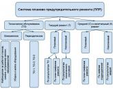
- Preventive maintenance and its role in production
- Planned preventive maintenance of equipment
- On the procedure for placing non-stationary objects of seasonal trade
- Provisions on the placement of non-stationary shopping facilities
- Decorative painting in kindergarten "magic curl" is a joint activity of the teacher and
- Synopsis of the organization and conduct of classes on cognitive development in the second junior group "Bird feeder
- New professions Where to get information about the right specialists
- Plasticine diplodocus. Sculpting lesson. How to easily make basic shapes from plasticine: a ball, cone, cylinder, plait, brick How to make a cylinder from plasticine
- Rating of recruiting agencies
- Rating of recruiting agencies