Four-sided milling machine. Price for a four-sided milling machine
Among huge amount woodworking equipment, there are such machines that can process parts simultaneously from four sides, and they are called four-sided planers. The working element of this equipment are rotating cutters or heads with knives. Since processing takes place simultaneously on four sides, at least four working elements can be installed. Why buy quadrilateral machine on wood, what is its main difference and what is the price of equipment? Let's figure it out.
Features of 4 Sided Woodworking Machines
According to its functionality, the four-sided woodworking machine can perform several jobs at the same time: jointing, milling, profiling and thicknessing. That is, as you can see, the design of the machine is quite complicated, and we'll talk about this further.
Machine tools are commonly used to create lumber with a profile or a flat surface. Feature is that all this work can be done in one pass. On these four-sided machines, you can produce such wooden products: floor or parquet boards, glued laminated or profiled timber, skirting boards, lining, imitation timber and any molded or window elements. The four-sided woodworking machine is one of the varieties of longitudinal milling equipment. Therefore, all 4-sided devices on the tree can be conditionally divided into:
- Longitudinally milling.
- Thickness planer.
Planer on wood is used for planing a part to a specified thickness simultaneously from two sides. The four-sided thicknesser is initially planer and additionally has the ability to profile. This machine can produce shallow profiling, with a simple design of a small beam lock.
Longitudinally milling is designed for cutting material along the length to the specified size. Profiling this woodworking machine can perform any complexity. Taking into account the thickness of the planed wood, the lower knife shaft moves in the vertical direction simultaneously with the table top of the device.
Simultaneous processing of wood from four sides significantly reduces the time spent, and, accordingly, increases the productivity of any production. It is this difference that makes the four-sided woodworking machine the optimal equipment in the construction and furniture sectors.
Main criteria when choosing a woodworking machine:
- system and speed of feed of a bar;
- section of lumber for possible processing;
- machine weight;
- processing power;
- equipment price.
All four-sided machines can be classified according to the following features:
- presenting material in different ways.
The design of various components of a four-sided machine
To understand how the equipment works, it is necessary to consider the design features of the machine, which includes a large number of nodes, the main of which we will consider in more detail.
Cast iron bed
At the base of the machine is cast iron, it can have a different alloy and inserts, but it necessarily absorbs a certain amount of vibration during the operation of the equipment and, due to its large mass, almost reduces it to zero. For feeding the timber, the material from which the loading table is made is also important. For more convenient work, there may be auxiliary elements on the table: pressure rollers, a ruler, and so on.
Tools
 The number of spindles in a woodworking machine can be set from 4 to 8 or more. All of them, taking into account the model, are installed in different working units with independent electric motors. Fixed spindles cantilever. The number of spindles depends on the complexity of the profile, the thickness of the wood removal and the needs during the processing of the timber.
In the milling four-sided longitudinal machine there are working rollers, which are divided into: right and left, upper and lower. The main ones in the design are rollers with spindles, which are horizontally below and vertically on the right. The exact number of planing and tinting elements provided in the equipment depends on its power, performance and class.
V model range From different manufacturers of four-sided machines, there is a universal equipment with an element that can replace any of the vertical or horizontal spindles. It can handle the product at an angle, that is, it can be used as an inclined roller.
At the request of the customer, a saw shaft can be installed on some models of equipment. This device can cut a wide product along the length, which allows you to create a material with regular geometric shape and the required section.
Feeder
Broaching, feeding and unloading of products in four-sided woodworking equipment is driven. All work is done with the help of pressure and toothed rubberized rollers. This system can be controlled from a remote control, but the price of these computerized devices is higher.
Control and security system
 The protective cover reduces noise during the processing of the cant, and also protects the operator from various injuries. The sight glass can be additionally equipped with lighting.
The woodworking four-sided machine is controlled from the panel. Depending on the equipment model, several actions can be performed from the control panel: feed rate products to tools, setting the dimensions of the processed timber, setting the position of the spindles relative to the diameter and detail of the nozzle (if the equipment is fully automatic), turning it on and off.
The presence of a hydraulic spindle and a joyter and the number of working tools depend on the type of equipment. These devices sharpen the knives directly during the processing of the product.
The price of woodworking machines
 You can buy a longitudinally milling four-sided machine for wood in specialized hardware stores. But the most profitable would be to buy the machine directly from the manufacturer. Naturally, this applies only to domestic units, foreign ones (Italian, German, Chinese, Thai, etc.) are more expensive to purchase directly, because the price of its transportation will cost more than the cost of the equipment itself. In large metropolitan areas, for example, St. Petersburg, Moscow, Nizhny Novgorod or Kazan, it is possible to rent equipment from industrial companies or by installments directly from the manufacturer.
Basic moments, which you need to pay attention to before purchasing equipment, these are:
- Reliability of operation.
- Accuracy.
- Service availability.
- Performance.
- Equipment price.
If a four-sided woodworking machine is planned as an addition to an already operating line, then the dimensions of the equipment must also be taken into account.
The price of a four-sided woodworking machine depends on such factors:
- functionality;
- Class;
- remoteness of the manufacturer;
- manufacturer.
It is important to consider at the time of purchase technical specifications, especially, the combination of different processing options, the speed of work and the weight of the equipment.
Any electrical equipment is a machine that, over time, can break and wear out. Therefore, when buying, it is advisable to select the most durable and wear-resistant machine. Thus, you will have to pay less for service, and there will be much less interruptions in work. And this will directly affect the profitability of the work.
Today, entrepreneurs in the first place is not only profit, but also the safety of employees. Therefore, it is important that the equipment has a metal protective casing with sound insulation, limit switches, electric brakes, etc.
Processing of products on the equipment should be of the highest quality and accuracy. For this, it is important that the device has done static and dynamic balancing all fixing parts: rotating spindles and tools.
There are firms that have just begun to take their place in the domestic market, because the price for this equipment is lower, and the quality is at the proper level. For example, these companies include the German brand beaver. To reduce the cost of their products, the company has located production in China and Taiwan, but the parts for assembly are made in Germany. Buying a little-known Taiwanese or Chinese brand is almost like a lottery. Moreover, it will be very difficult to find spare parts for this model. Therefore, cheap models do not even need to be considered.
To ensure the safety of the machine CDK 4-3 It has:
− bolts for connection to the workshop ground loop;
- closed on all sides the working area of the saw, except for the opening at the exit of the processed material;
− two rows of claw curtains ensure the constancy of the wedging chain with an angle 55−650 when processing material thickness 6−120 mm;
− riving knife;
− a brake device that ensures the stop of the saw shaft within no more than 6 seconds from the moment it is turned off;
- interlocks that prevent the machine from starting when the caliper doors are open, the claw curtain is raised, the feed chain guard is removed;
- blocking the feed to the fixed saw;
− local lighting lamp.
2.2 Four-sided longitudinal milling machines
1. Purpose and scope of the machine
On four-sided longitudinal milling machines, flat and profile processing of straight-line blanks is carried out from four sides in size in one pass. The machines of this group, depending on the width of the milling, are divided into light (moulding) for processing profile furniture and joinery parts up to 160 mm wide, medium for processing joinery flat and profile parts up to 250 mm wide and heavy for processing molded products and sawn timber of mass production with a width of up to 650 mm.
2. Main technical data
|
The largest processing dimensions, mm: | |
|
Number of cutter heads, pcs. | |
|
Cutter head diameter, mm | |
|
Frequency of rotation of cutter heads, min -1 | |
|
Total power of electric motors, kW | |
|
Workpiece dimensions, mm maximum width maximum thickness minimum length | |
|
Total installed power, kW | |
|
Overall dimensions maximum (length, width, height), m |
3. Machine controls
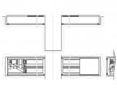
Figure 4General formFour-sided longitudinal milling machine
1 - bed;
2 - lower spindle;
3 - left spindle;
4 - molding support;
5 - upper spindle;
7 - pressure rollers;
8 - clamp support;
9 - handwheel;
10, 14 - rollers; 11 claw protection;
12 - side clamp;
4. Brief description of the machine structure
Figure 5. Principal diagrams of four-sided longitudinal milling machines:a - with concentrated feed;b - with distributed feed
In four-sided machines operating according to the most common planer-thickness scheme (Figure 5 a), horizontal spindle 5 creates a base surface on the bottom face of the workpiece, so the workpiece must pass over this spindle without deforming. In some machines and automatic lines, various devices are used to prevent deformation of the workpiece, for example, to create an intermediate base, to replace the movable basing along the face with a rigid basing along the edges, etc.
When using an intermediate base (Figure 5 b) the machine is equipped with an additional cutter head 5 , processing the workpiece not over the entire face, but milling two shallow ( 2...3 mm) groove on the edges. A significant reduction in cutting forces, and consequently, feed resistance forces, allows to reduce the traction force. Therefore, when processing such grooves, it is possible to significantly reduce the pressure of the feeding organs on the wood. According to the intermediate base of the workpiece developed in this way, basing is carried out on a special mounting surface of the machine 13 when processing the entire face with a lower milling head 6 . Further basing occurs, as usual, along the entire lower surface. (
Depending on the complexity of the profile, surface roughness and processing accuracy, machines can have up to 10 spindles. Right vertical spindle 8 creates a base surface on the side of a part. Left vertical 12 and top horizontal 1 spindles of four-sided machines process the part to size, like thickening shafts. If required, you can also perform profiling. Vertical spindles can be located opposite each other (Figure 5, a) or sequentially (Figure 5 b). Medium and heavy machines have additional horizontal and vertical spindles for profiling either side of the part or dividing it with circular saws into several parts along the width.
The spindle assembly of the four-sided machine is a steel sleeve, in the bore of which a dynamically balanced spindle is installed on high-precision rolling bearings with preload. The cantilever part of the spindle has a seat neck for a cutting tool 180-250 mm long for horizontal and 120-140 mm for vertical spindle assemblies. Spindle speed - 5 000 ... 12 000 min -1. The drive in rotation from the electric motor - through flat or flat-toothed belt transmission. The radial runout of the spindle seat does not exceed 1-2 micrometers. It is traditional to install a shell cutter or cutter head on the landing neck. Primarily for medium and heavy machines, there are devices for dynamic milling of cutters. Such a jointing is carried out with a soft abrasive for both straight and profile knives at operating speeds, which makes it possible to bring all knives to the same blade diameter.
The spindle assembly is made maintenance-free, since the plastic long-life grease is laid in the bearings for the entire period of their operation. In some machines, the cutting tool is mounted directly on the shaft of an electric motor powered by high frequency current. The spindles have vertical and horizontal adjusting movements with the help of screw pairs.
In light machines, horizontal and vertical cutter heads are cantilevered on a unified support. In medium and heavy machines, to give greater rigidity, the cutter heads are located between the supports, one of which is removable for quick tool changes.
The feed mechanisms of four-sided longitudinal milling machines are divided into two main groups: concentrated and distributed. According to the concentrated scheme (Figure 5 a) the feed mechanism is located in front of the cutter heads and the workpieces pass through the machine, pushing each other. Top feed drive 3 and lower 4 rollers is carried out from an electric motor through a V-belt variator, worm gear, chain and gear drives. Lateral clamping of the workpiece to the guide rulers 7 first carry out flat springs 10 , then roller clamps 11 , top clamp - spring-loaded rollers 2.
Since, according to the concentrated feeding scheme, the traction force is developed by only two pairs of rollers, a large amount of their clamping is required, which leads to crushing and slipping of the part. Therefore, with a concentrated scheme, roller-conveyor and two-conveyor feeds are more reliable. Since the blanks according to this scheme pass through the machine, pushing each other, sufficient accuracy is required in the preliminary trimming of their ends.
According to the distributed scheme (see Figure 5 b) feed rollers 3 much more (8... 14) , and they are distributed throughout the machine. Under these conditions, the feed force developed by each roller is sufficient to overcome the feed resistance forces of only one cutterhead. The design of the rollers allows processing workpieces of small length (from 200 mm). Distributed feed is especially reliable when machining parts with oblique ends. The working surface of the rollers is corrugated, smooth metal or rubberized.
The drive of the feed rollers is carried out for most machines from an electric motor (for heavy ones, most often from a hydraulic motor) through a V-belt variator, worm gears and dual chain drives or cardan shafts. The feed rate is regulated, as a rule, smoothly, either by a variator or, more promising, electronically. The feed rate for light and medium four-sided machines ranges from 5 ... 45 m / min, for heavy machines - up to 80 and even up to 200 m / min. Manual loading of parts into the machine at speeds above 30 m/min is not possible, so four-sided machines are equipped with automatic loading devices.
The main indicators of any woodworking production are high-quality work and productivity. To fulfill these conditions, you must have the appropriate equipment. One such equipment is a four-sided woodworking machine.
Design and scope
Relatively recently, in the production of wood processing, designs have appeared that combine several operations. Processing of wooden products in this case occurs from four sides at once. This equipment is most often used for milling and jointing.
The woodworking machine consists of:
- spindle section;
- part feed unit;
- equipment parameter control systems.
On the one hand, there can be several processing heads, which makes it possible to reduce the cost of manufactured products and reduce the time for performing a certain operation.
The four-sided machine is designed to perform the following operations:
- Milling. On the working heads of the equipment, instead of planing shafts, disk cutters are installed, which makes it possible to do longitudinal milling. To carry out processing with finger cutters, it is necessary to periodically stop the parts, however, this is not provided for by the design;
- Planing and jointing. This can be done using shafts with blades of a certain configuration mounted on them. The design of the machine makes it possible to perform both finishing and roughing;
- Reiming and profiling.
Most often, such models are used to create lumber with a flat surface or profile. All work can be done in one pass.
With the help of four-sided machines, you can make products such as:

Classification and differences of machines
All four-sided woodworking machines can be divided into:
- thickness planer;
- longitudinal milling.
Longitudinally milling machine used for cutting along the length of the material to the desired size. This woodworking equipment can perform profiling of any complexity. The lower shaft of the knife, taking into account the thickness of the planed wood, moves along with the table top in a vertical direction.
Planer used to cut a part to a specified thickness simultaneously from two sides. It is initially planer, but has an additional profiling function. Such a machine can produce shallow profiling with a simple small bar lock design.
Processing wood on four sides at the same time helps save time and increase productivity. That is why in the construction and furniture sectors, four-sided machines are the optimal equipment.
Main selection criteria
Considering that a machine for complex woodworking is expensive equipment, it is important to consider when choosing it specifications and all the nuances of the design. Equipment performance depends on:
- speeds and systems of giving of a bar;
- degree of processing and dimensions.
Choosing the optimal machine model you should pay attention to:

In order to precisely position the workpieces relative to the machining center, a system of sensors is required. In addition, when analyzing the model, one should take into account the cost of components, the degree of remoteness of the manufacturer's service centers and the terms of the warranty.
The design of the machine units
To understand the principle of operation of the equipment, it is necessary to consider design features of the machine, which includes many nodes.

In some models of equipment, a joyter, a hydraulic spindle and a number of working tools are included. Such devices sharpen knives directly during processing of the product.
Buying a machine
Longitudinal milling machine can be purchased at construction specialized stores, but it is better to buy it directly from the manufacturer (if we are talking about domestic manufacturers). Equipment can be rented or purchased by installments.
Before you buy the equipment, you need to pay attention to the following main points:
- performance;
- accuracy;
- operational reliability;
- service availability;
- equipment price.
If a four-sided woodworking machine will be an addition to an already running line, it is important to consider its dimensions. At the time of purchase, it is necessary to take into account the technical parameters and combination various options processing, weight of equipment and speed of work.
Some companies providing such equipment are still little known. The price of their products relatively low, but the quality is adequate. For example, the German brand Beaver. The cost of their products is low due to the fact that the production is located in Taiwan and China. But parts of the assembly are made in Germany.
When choosing equipment, you should not consider cheap Chinese-made models. It should be borne in mind that it will be very difficult to find spare parts for them.
Service maintenance
 Any machine tends to break down over time, the constituent parts wear out. In order to have fewer interruptions in work for such reasons, it is advisable to choose the equipment that is most durable and wear resistant.
In addition to productivity, it is important that the machine is as safe as possible. Therefore, the presence of limit switches, electric brakes and metal protective cover with soundproofing.
Processing on the machine of products should be as accurate and high-quality as possible. For these purposes, it is important that the device has static and dynamic balancing of all fixings of parts.
When operating the equipment, it is necessary to adhere to the rules specified in the instructions for it. It is impossible to process workpieces that are larger in size than those stipulated by the rules. It is essential to carry out preventive and repair work to keep the equipment in working condition.
It is very important to set up the machine correctly., taking into account not only its dimensions and weight, but also the dimensions of wooden blanks. The operator should not face the difficulties associated with the supply of material.
Pros and cons of equipment
One of the most positive qualities of four-sided machines is high productivity. To achieve optimal results, the design must be equipped with a program numerical control unit. Then the influence of the human factor will be minimal.
The conditions for the correct compilation of the program must be met, and an accurate measurement of the workpiece being processed must be made. In the optimal configuration, the equipment is designed for processing cylindrical workpieces and rectangular timber. Jointing and milling of sheet materials can be performed on both sides. Features of the operation of machines of this type are the following factors:

The main disadvantages of four-sided woodworking machines are the high cost and complexity of setup. However, in a production line, these indicators are not significant.
Price: $51,000 (3 227 848 ₽)
Price: 0 c.u. (0 ₽)
Professional series. The perfect combination of high reliability woodworking machine with...
Price: $40,500 (2 563 291 ₽)
The perfect combination of high reliability woodworking machine with high technical...
Are you looking for productive and inexpensive equipment that allows you to work with any type of wood? Products from the catalog of the TekhLesProm company fully meet these requirements. The company sells four-sided longitudinal milling machines that combine high resource with precision.
Scope of four-sided longitudinal milling machines
The equipment allows simultaneous flat and profile processing of four surfaces of a wooden workpiece. The machine has a massive frame on which the table, cutting tool and feeders are fixed. The equipment is driven by electric motors.
Four-sided longitudinal milling machines are universal devices, most widely used when working with the following products:
- skirting boards;
- joinery;
- timber for window and door frames;
- solid wood flooring.
TekhLesProm specialists will provide qualified assistance in the selection of woodworking equipment, as well as take care of delivery, installation and commissioning.
Popular goods
Price: $29,200 (1 848 101 ₽)
Price: $118,000 (7 468 354 ₽)
TO category:
Woodworking machinery
Four-sided longitudinal milling machines
Four-sided longitudinal milling machines are designed for flat and profile processing in one pass of all four surfaces of the workpiece or board. Sometimes saws are installed on the same machines to separate workpieces in width or thickness.
Design
The working bodies of a four-sided longitudinal milling machine (Fig. 1) consist of two horizontal spindles - upper and lower - and two vertical spindles - right and left. In machines of some models, a fifth lower horizontal spindle is additionally installed. Material supply roller-caterpillar or roller. The machines are equipped with guide lines and clamps. All elements are fixed on a cast frame.
In the process of work, blanks (boards) are continuously fed into the feeding mechanism manually or with the help of a feeding device. The workpiece captured by the feeders enters the knives of the lower horizontal cutter head. The lower cutter head cuts the lower face, creating the first base surface, then the workpiece enters the cutter head of the right vertical spindle, which, while processing the edge, forms the second base surface. Based on these two surfaces, the workpiece moves on to the cutterhead of the left vertical spindle, planing the second edge, and finally, the upper horizontal head cuts the top face.
Spindles are usually mounted on calipers that allow you to change their position when adjusting in the vertical and horizontal planes. This is very important, since four-sided longitudinal milling machines are designed to process workpieces (boards) of various sizes, both in width and in thickness. Vertical machine spindles can also be tilted in a plane perpendicular to the feed direction.

Rice. 1. Scheme of a four-sided longitudinal milling machine: 1 - support of the fifth (moulding) spindle, 2 - support of the upper horizontal spindle, 3 - upper horizontal spindle, 4 - right vertical spindle, 5 - support of the lower horizontal spindle, 6 - support of the feed mechanism, 7 - lower horizontal spindle, 8 - horizontal clamps, 9 - left vertical spindle, 10 - left vertical spindle support, 11 - molding spindle, 12 - ruler guides, 13 - base plate, 14 - vertical clamp
The additional lower fifth spindle And is often called a moulder, it is designed to select a profile in the lower face of the workpieces and to separate them in width or thickness into separate bars. In the first case, profile cutters are attached to the spindle, in the second case, circular saws with a diameter of up to 350 mm. In C16-4A machines, the molding support can be rearranged from the lower position to the upper one for sampling a deep profile on the upper face of the workpiece (board). In addition, these machines provide the ability to rotate the additional spindle by 90°, which allows it to be used for dividing workpieces by thickness.
The spindles rotate at a frequency of 5000-6000 rpm from individual electric motors. Often, machines are equipped with electric motors with elongated shafts (Fig. 141), which are simultaneously spindles.
Spindles made separately from electric motors are connected to them by couplings or belt drives; in this case, electric motors operate on industrial frequency current, in all others - on increased frequency electric current (100 Hz).
Some models of four-sided planers are equipped with ironing knives (Fig. 3) mounted directly behind the first horizontal lower spindle. Of the three installed ironing knives, two work, and the third is recessed below the guides by an eccentric and is in reserve. Ironing knives remove small irregularities from the processed lower layers of the workpieces. Each knife is installed in a sliding box at a certain angle to the direction of movement of the workpieces. The knives can be moved in height (each separately) by eccentric rollers. This is necessary to change the thickness of the chip being removed.
Ironing knives remove long chips that exhausters cannot remove, so the machines are additionally equipped with a chip crusher powered by a separate electric motor.
If the chips are clogged under the ironing knives, then the front surface of the workpiece may form bulges, bumps, grooves and depressions. If this defect is detected, the correct installation of the knife is checked. By turning the eccentric, the knife is drowned, the box with the knife is removed from the machine for inspection and the reserve knife is put into operation.
Chips are driven under the knife when there is a gap between it and the chip breaker (local or along the entire length) or if the knife protrudes from the chip breaker by less than 1-2 mm, and also when the back edge of the knife is below the level of the chip breaker. Having eliminated the shortcomings, the box with the knife is put in place.

Rice. 2. An electric motor with a shaft that simultaneously serves as a vertical spindle of a longitudinal milling machine: 1 - body, 2 - nut, 3 - cutter, 4 - spindle lifting mechanism, 5 - caliper guides, 6 - screw for moving the spindle in a horizontal plane
With roller-caterpillar feed, the chain and rollers are driven by a single drive (often with a variator for stepless speed changes). The feed rate is in the range of 4-42 m/min. The top rollers can be adjusted in height.
The roller feed mechanism is located in the head of the machine, however, the rollers can be dispersed along the machine. Their surface is corrugated or smooth. If the rolls are mounted behind the upper cutterbar, they are sometimes covered with rubber, which gives better grip on the surface of the workpiece and at the same time maintains the roughness class of its processing.

Rice. 3. Ironing knives: 1 - knife, 2 - box, 3 - screw, 4 - eccentric roller, 5 - chip crusher
Guide devices consist of steel plates and guide rulers. The plates form the supporting surface for the workpieces. The base plate of the front table in front of the lower horizontal cutter head is set in height by turning the handwheel of the screw mechanism, and this achieves a change in the thickness of the chips removed from the workpiece. This thickness should not exceed the height of the irregularities on the workpiece surface.
Four-sided longitudinal milling machines are equipped with a centralized control system, which provides for a blocking that prevents breakage of individual elements of the machine if the machine operator makes a mistake in controlling the machine.
Four-sided longitudinal milling machines C10-2, C16-5, C16-4A, C25-01 have much in common in design and differ mainly in size and individual cases- the order of placement of the working bodies, the power of the electric motors of the drives.
The C10-2 machine is designed to simultaneously process four sides of blanks and boards up to 100 mm wide (as indicated in the model index) and up to 50 mm thick. All C16 machines are designed for processing blanks and boards up to 160 mm wide and up to 80 mm thick; C25-01 machines - for blanks up to 260 mm wide and up to 125 mm thick.
The C16-4A machine is the main one in the group of four-sided longitudinal milling machines. It is designed for planar milling of boards, bars and planks simultaneously from four sides.
The machine bed is cast iron, box-shaped. Electric motors are fixed on the supports of the frame, cutter heads are installed on their shafts. Guide lines and spring-loaded rollers are also fixed on the bed for clamping workpieces to the machine table and guide line.
The support with the electric motor of the lower horizontal knife head (the first in the feed direction) can move vertically and is fixed with an eccentric clamp. The caliper with the electric motor of the right vertical head (second in the feed direction) can move in the transverse direction and is fixed with a clamp. The caliper of the left vertical head (the third in the feed direction) moves vertically with a handwheel and is fixed with a clamp; in the axial direction, the position of the caliper is changed and fixed with screws.
To set the feed rollers, cutterheads and clamping elements to the size of the material to be planed, the machine provides the appropriate scales. A molding counter is installed on the machine, the control panel is located on the gable part of the bed, the electrical equipment of the machine is placed in the electrical cabinet. The blanks are fed into the machine manually and with the help of a magazine, they are picked up by the feed (two lower and two upper) rollers from the drive, which includes an electric motor, a variator, a gearbox and a gear transmission. The feed rate is infinitely variable.
The position of the workpiece moving during processing is determined by the support tables and side guides.
All spindles have guards that also serve as chip traps. A board thickness limiter and claw protection are installed in front of the feed mechanism.
The machine control system ensures that the feed mechanism cannot be switched on and operated when at least one of the electric motors of the working bodies is turned off, and the electric motors cannot be switched on when the guards are not installed.

Rice. 4. Four-sided longitudinal milling machine S25-01: 1 - upper knife shaft support, upper knife shaft setting handwheel, 3 - clamping device adjustment handwheel, 4 - clamping device block, 5 - feed mechanism adjustment handwheels, 6 - control panel, 7 - block with a feed mechanism, 8 - exhauster receiver of the left vertical spindle
The power of the electric motors of the machine and high speed feeds allow the use of high-speed processing modes during the operation of the machine.
The C16-4A machine as a machine with continuous processing, with a stepless feed rate, can be included in an automatic line.
The four-sided longitudinal milling machine C25-01 is also the basic model. The roller feed mechanism with stepless speed change is installed in the front block of the bed. The design of the machine allows it to be supplemented with an automatic magazine feeder, for the drive of which an asterisk is provided on one of the shafts of the machine feed mechanism. The setting of the feed rollers for the thickness of the material is done by handwheels. Clamping elements located in the area of vertical spindles are mounted in common block. When adjusting the clamping elements in height, the block moves in a vertical plane with a handwheel. The upper horizontal knife shaft is mounted on a support on the left side of the bed. To adjust it in height, a screw mechanism for moving the caliper with a handwheel is provided. The machine control panel is located at the front of the machine where the workplace machine operator.
Operating mode selection
The operating mode is selected according to the power of the most loaded electric motor and according to the roughness class of the treated surface. These indicators are calculated in the same way as for thicknessing machines, but for all electric motors of the working bodies. Then, the feed rate is selected according to the power of the most loaded engine, provided that the required class of roughness of the machined surface is obtained.
Machine setup
Four-sided longitudinal milling machines in terms of settings are the most complex of the entire group of longitudinal milling machines. They set up cutting units, clamping elements and feeders.
The upper generatrix of the cylindrical cutting surface of the lower horizontal cutter head, located in front of the rest of the cutting tools of the machine, must coincide with the working surface of the rear (fixed) table or be 0.02-0.05 mm higher than it. The position of the cutter head relative to the back table is checked in the same way as when setting up a jointer, i.e., with a control bar. The coincidence of the horizontal tangent to the cutting surface and the working surface of the rear table is ensured by moving the height of the cutter head spindle support, turning the eccentric roller on which the support rests, or moving the support by other devices.
The front (movable) table of the machine is installed below the rear by the amount of the layer of wood that is cut off from the face of the workpiece. This size depends on the machining allowance and ranges from 1 to 3 mm.
If the Design of the front table provides for the possibility of moving in height only its sponge located at the cutter head, then the thickness of the layer being cut off determines the position of this sponge. This design of the table allows you to easily change the thickness of the removed layer of wood.
When adjusting the lower horizontal cutter head for profile milling, in addition to setting it in height, it is necessary to adjust its position along the width of the table. For adjustment, a reference part or a piece of a previously processed part is used. The part is placed on the back table above the cutter head and pressed against the right vertical ruler.
If subsequent milling of the edges of the workpiece is provided, then spacers with a thickness equal to the thickness of the layer of wood cut off by the right cutter head are placed between the reference part and the ruler. The head is installed in horizontal and vertical directions along the reference part and fixed.
The upper horizontal cutter head located after the lower one is set so that the distance from the cutting edges of the knives to the table located under the head is equal to the thickness of the processed workpieces.
If the upper cutter head is located first in the course of the workpiece, then the upper table is also set up at the same time, to the working surface of which the workpiece is pressed by the upper face when milling its lower face with the lower horizontal cutterhead. This table is installed above the rear table of the lower horizontal cutter head parallel to the table surface to a height equal to the thickness of the workpiece to be milled. The head is installed so that the horizontal cutting plane coincides with the working surface of the upper table.
For profile processing of the plate, the horizontal upper cutter head is adjusted in the same way as the profile lower one.
The right vertical cutterhead (or cutter) is installed in a horizontal plane so that it is possible to remove a layer of wood of a given thickness from the right edge of the workpiece. To do this, the cutting edge of the tool, which has the smallest radius of rotation (for profile milling of the edge), should protrude to the left beyond the plane of the right front vertical ruler by an amount equal to the thickness of the wood layer being removed from the most protruding part of the profile. The left vertical head (cutter) is set in the horizontal direction to the specified width of the part.
The working surface of the left guide ruler is installed in a plane tangent to the circle of rotation of the cutting edge of the tool, which has the smallest radius, parallel to the direction of feed of the workpiece. In the vertical direction, the cutting tool is installed so that its cutters overlap the thickness of the part,
For profiling the edges, the cutters on vertical spindles are adjusted to the reference part. The cutter is moved in height, achieving the coincidence of its profile with the profile of the reference part pressed against the machine table. If, after profiling the edges, it is planned to remove the layer of wood from the bottom layer of the workpiece, then the cutters are adjusted according to the reference part laid on the gasket. The thickness of the spacers should be equal to the thickness of the removed layer of wood. The supporting surface of the rollers or caterpillars should protrude 0.3-0.5 mm above the table surface. The lower feeders are adjusted by moving them in height.
The upper feed rollers are set in height at a distance from the surface of the lower rollers or caterpillars, equal to the thickness of the processed workpiece or slightly less than the thickness (by 1-1 (5 mm). The value of the pressure force of the upper feed rollers on the workpiece is regulated by spring compression. to overcome the resistance to feed; at the same time, too much pressure of the rollers on the workpiece should not be created, as this causes additional feed forces.
When adjusting the vertical clamps, adjust their position in height and set the value of the clamping force.
All vertical clamping elements located in front of the upper cutter head are set 1.5 mm below the horizontal plane of the longitudinal milling of the head, so that they press the workpiece, even if its upper face is not milled, and ensure the normal operation of other cutting tools of the machine. Vertical clamping devices after the upper cutter head are set below the horizontal cutting plane of the head by 0.5 mm.
Horizontal left clamps are set at the level of the cutting plane of the left vertical head (cutter). Clamps that serve to support chips in front of cutting tools (horizontal and vertical) are installed at the level of the cutting plane of the tool, parallel to the feed direction.
Clamps must prevent the workpiece from vibrating or moving away from the base surfaces. The amount of pressure is adjusted by tightening the springs.
After finishing the machine settings, it is necessary to remove foreign objects from the zone of cutting tools and other mechanisms of the machine, check by hand the ease of rotation of the cutting tools, put all the guards on the machine. Then turn on the machine and carry out trial processing of workpieces. After checking the dimensions and quality of the parts obtained, the machine is adjusted if necessary.
A properly configured machine should ensure the accuracy of the dimensions and shape of the machined parts with deviations from the straightness of the side edges of no more than 0.2 mm over a length of 1000 mm; from the parallelism of the side edges - no more than 0.3 mm over a length of 1000 mm; from the perpendicularity of the edge and face - no more than 0.15 mm over a length of 100 mm; from uniformity in thickness - according to the 2nd class of processing accuracy.
After pre-setting the machine for a given processing size, two or three test workpieces are processed and, based on the measurement results, they are considered to be a complete setting or adjustments are made to it.
The reference part used for tuning is a copy of the part, made with an accuracy one class higher than the accuracy class of the part. The standard is made from hardwood or, better, from lignofoil. The dimensions of the standard must be checked periodically.
It is permissible to use a piece of a previously machined part when setting up machines for rough processing of parts according to the 3rd accuracy class. The conditions for processing test parts, according to which the machine is adjusted, and the parts themselves must be characteristic of a given batch of workpieces.
When setting up, you must use accurate measuring tools.
Work on machines
Four-sided longitudinal milling machine is served by two or three workers. Before starting work, you should make sure that there are a sufficient number of blanks and that the exhauster system is in good condition,
Before starting the machine, they check the serviceability and correct position of all protective devices, and before setting up, turn off the machine's shield, on which the push-button control is located, in order to prevent the possibility of turning on the machine by mistake.
In a four-sided longitudinal milling machine, boards with wingedness, with deep risks or curves, as well as overdried, with large warping, cannot be sent.
In the process of work, the machine operator, standing at the feeding table, makes sure that the boards on the table rollers go in one row, without significant distortions, correcting incorrectly lying boards manually. If the machine is not equipped with a feeding table, then the boards or blanks from the stack are laid on the table in front machine. The material should be fed without inter-end breaks. When planing short workpieces, inter-face gaps lead to the stoppage of the workpiece in the machine, which can lead to the formation of processing defects on the machined surface (tearing across the part, arson). If end-to-end breaks are unavoidable at a given feed rate, the feed rate should be reduced.
The operator must follow right position stops that limit the size of the supplied workpieces, since the entry of workpieces with excessive allowances into the machine can lead to machine breakdown or overheating of the electric motors.
The dimensions of the workpieces after milling should be controlled every 20-30 minutes using gauges. If, during operation, the rotational speed of one of the working bodies drops (detected by the appearance of noise that is unusual for normal operation machine), the machine operator must immediately turn off the feed until the working parts rotate at the required speed. When slipping of the feed rollers, indicating a weakening of the clamps, you should stop the machine and, after examining it, eliminate the cause that disrupts the normal supply of workpieces to the machine.
When stopping the machine, check the condition of the electric motors and belt drives. If unacceptable heating of at least one electric motor is detected, the machine must be stopped and the cause of the heating must be eliminated. After 1.5-2 hours of work, it is necessary to joint and finish the knives.
When soiled, tables or rollers should be cleaned. The reason for the appearance of chips, tears, moss and hairiness on the treated surface may be a large thickness of the removed layer of wood. A chopped surface or a large difference in wavelength may be due to slack in the bearings.
Machine construction. Four-sided longitudinal milling machines are produced for processing with the greatest cross section blanks in width and thickness 100X50 mm (S10-3), 160X80 mm (S16-2A, S16F-1A) and 250X125 mm (S26-2M, S25-1A, S25-2A). For the processing of parquet boards, there are machines with the largest milling width of 70 mm (PARK7) and 100 mm (PARK9).
For mechanization of loading, store loading devices are used, attached to the machine, or special feeding tables. For unloading operations, the machines are equipped with post-machine conveyors and automatic stackers of finished parts.
The C26-2M four-sided longitudinal milling machine is designed for processing boards and squared parts. On the box-shaped bed, the calipers of the horizontal lower spindle, vertical right and left spindles and the upper horizontal spindle are placed in series. The machine can be equipped with an additional molding support, which is designed for making grooves in the part or cutting it into pieces when leaving the machine.

Rice. 1. Four-sided longitudinal milling machine S26-2M: 1 - bed, 2,3,5 - spindles, 4 - molding support, 6 - table, 7 - pressure rollers, 8 - pressure support, 9 - handwheels, 10, 14 - rollers, H - claw protection, 12 - side clamp, 13 - guide ruler
The cutting tools are mounted on spindles, which are driven by individual electric motors through a belt drive. The machine is equipped with a claw protection that prevents the back ejection of the workpiece from the machine. Nearby is a bar that serves as a limiter for the supply of blanks with an unacceptably large allowance.
The feed mechanism of the machine is located in front of the working spindles and consists of two lower non-driven and two upper driven rollers. For better grip with the workpiece, the upper rollers are made corrugated. The rollers are driven by a separate electric motor with an adjustable pulley through a V-belt (variator) and a system of gears. The variator allows you to smoothly change the feed rate from 7.5 to 42 m/min. Spring-loaded rollers 7 are mounted on the support, pressing the part to the table. From the side, the workpiece is pressed by a spring clamp to the guide ruler.
Machines for processing parquet boards are similar in design. A distinctive feature of the machines is the presence of a conveyor feed mechanism for processing short workpieces. It is a two-chain driven conveyor with spring-loaded grips (thorns). The spikes provide reliable grip and feed of workpieces that differ in the size of the machining allowance up to 2 ... 3 mm.
Selecting the operating mode. The mode of operation of the machine is selected depending on the nominal dimensions of the part in terms of width and thickness, the complexity of the resulting profile and the required quality of processing.
According to the given dimensions of the part and the known allowances for processing, the thickness and width of the layer to be removed by each cutting tool is calculated. This data is used to select the allowable feed rate from the condition of the maximum load on the electric motors of the cutting mechanisms. The choice is made according to the graphs given in the machine manual, or by calculation using formulas. Often the top cutter head or left cutter is the busiest, producing deep, complex profiles. If increased requirements are set for the purity of the resulting surface, then the limiting speed of the workpiece should be assigned from the condition of the allowable feed per one cutter.
Setting up machines. Setting up four-sided longitudinal milling machines is a complex and time-consuming operation. To reduce the number of reconfigurations, workpieces of the same standard size should be processed in batches. The smallest batch size is chosen so that the end of its processing, if possible, coincides with the replacement of blunt cutting tools. In addition, the next batch of blanks should be with such a type of processing that after skipping the first batch, a minimum time is required to change the machine. This allows you to increase productivity.
Setting up the machine consists in setting the tools to the specified processing dimensions, adjusting the movable tables and guide lines, as well as adjusting the feed and clamping elements. The sequence of tuning operations is determined by the type of processing, machine design, tuning method and tuning tools.
The scheme for setting up the machine according to a template or a reference part is shown in fig. 86. The template is installed in the machine, having previously moved the calipers, feed and clamping elements to a distance slightly exceeding the setting size. The template is pressed against the working surface of the table and the rear guide line. First, the guide rulers are adjusted so that their working surfaces are parallel to one another. Moreover, the rear ruler should be located tangentially to the cutting circle and protrude relative to the front ruler by the thickness of the layer being removed (2 ... 3 mm). The front line is aligned with the help of gaskets, the thickness of which is equal to the thickness of the layer to be removed.

Rice. 2. Scheme for setting up a four-sided longitudinal milling machine according to a template: 1 - rear table, 2 - template, 3 - rear ruler, 4 - front ruler, 5 - gaskets
Dimensional adjustment of cutting tools is performed from the material feed side in the following sequence: lower horizontal cutter head, left and right vertical cutter heads, upper horizontal cutter head and moulder (if necessary).
Dimensional setting for all cutting tools is similar and includes the following operations: releasing the caliper, adjusting the position of the cutting tool relative to the template, fixing the caliper. The caliper is moved with a removable handle or handwheel. The cutting edge of the knife is brought to touch the working surface of the template when turning the cutter head manually.
With another way of setting up cutting tools, built-in measuring tools are used: scales and dials. On fig. 3 shows the setting of the upper horizontal cutterhead of a four-sided planer. The caliper is moved with a handwheel, while counting the amount of movement on the scale. Having set the caliper in a predetermined position, proceed to the lining of the clamping elements. The rear clamping pads 9 at the upper cutter head are adjusted in height with nuts so that the distance from the table to the working surface of the pads is 2 ... 3 mm less than the setting size X. The clamping force of the pads is adjusted by changing the spring tension with nuts. The front clamp (chipbreaker) is adjusted in height by turning the nuts. The adjustment is carried out until the distance from the table to the working edge of the chipbreaker is equal to the setting size. The pressing force of the chipbreaker to the material being processed is adjusted with a handwheel, compressing or weakening the spring.
Roller clamping elements are configured as follows. Consistently unfasten all clamps in the course of feeding the workpiece and adjust their position relative to the table and guide rulers. When setting up, use measuring scales fixed near the adjustable element. The clamping force of the rollers is adjusted by changing the tension of the springs. The clamping force is selected depending on the type of wood and the size of the material being processed. Do not press the workpiece excessively against the table, as marks from the pressure rollers will remain on the surface of the finished part.
The lower feed rollers are set relative to the table, depending on the breed, size and condition of the material being processed. For hardwoods and thick blanks, the protrusion value is 0.2 ... 0.3 mm, for softwoods and thin lumber - 0.3 ... 0.5 mm.
The working edge of the front table is adjusted in height by rotating the eccentric roller with the handle of the adjustment mechanism. The table must be lowered relative to the rear table by the amount of the layer removed from the bottom layer, which is set using the reading device of the adjustment mechanism.
Then the upper feed rollers are adjusted in height, and a limiting bar and claw protection are also installed depending on the thickness of the workpiece being processed. The upper rollers are adjusted with a handwheel through a screw gear and rods.

Rice. 3. Adjustment of the upper horizontal cutterhead of a four-sided longitudinal milling machine: 1 - handwheel, 2 - chipbreaker adjustment handwheel, 3, 6, 7 - nuts, 4 - support, 5 - spring, 8 - chip breaker, 9 - clamping block, 10 - scale
The feed force is created by pressing the upper rollers against the material and the lower rollers through the springs. Spring tension is adjusted with nuts.
After finishing the dimensional adjustment of the machine, you should carefully inspect the moving parts and install guards. The pipelines of the exhauster network are connected to the chip collectors and the rarefaction of air in the chip suction system is turned on. By pressing the button, turn on the rotation of the cutting tools. After the previous spindle has set the full speed, the next one is turned on.
It is necessary to make sure that all cutting tools work without problems at idle, turn on the feed and process test pieces. The feed rate is chosen depending on the type of wood, the size of the allowance to be removed and the required quality of processing.
After processing, test parts should be measured with a measuring tool: a vernier caliper, an indicator thickness gauge or a caliber. The straightness of the machined surfaces is checked with a control ruler and a feeler gauge. Surface roughness is determined visually by comparison with a standard or measured with a TSP-4 instrument.
With proper adjustment of four-sided machines, the following deviations in the accuracy of machined parts are allowed: uniformity in thickness and width of the part along its entire length - according to the 12th grade; non-straightness of the side edges - no more than 0.2 mm over a length of 1000 mm; non-parallelism of the side edges - no more than 0.3 mm over a length of 1000 mm; non-perpendicularity of adjacent side surfaces - no more than 0.15 mm over a length of 100 mm.
Depending on the results of checking the test parts, the machine is adjusted and adjusted.
Work on machines. Machines that are not equipped with loading and unloading devices are usually served by two workers. After starting the machine, the machine operator places the next workpiece on the table, basing it with its edge along the guide ruler. After the workpiece is captured by the feed rollers, the machine operator prepares the next one.
To ensure continuous and uniform operation of the machine, the material should be fed without inter-face breaks, for this, when feeding short workpieces, the speed can be reduced.
The second worker must accept the finished parts, visually check the quality of their processing and stack them.
With mechanized loading and unloading of the machine, the machine operator must monitor the correct operation of all elements of the machine and near-machine mechanisms. The degree of loading of the cutting motors is controlled by an ammeter built into the control panel of the machine.
If the motors are overloaded, there is increased noise and knocking or a decrease in the speed of the tools, it is necessary to switch off the machine and find out the cause of the problem. common cause stopping the machine is its incorrect use. Workpieces with unacceptably large allowances or too thin, warped and irregularly shaped workpieces must not be fed. When jamming or stopping the workpiece, you must turn on the reverse feed and remove the workpiece from the machine. When moss and hairiness appear on the treated surfaces, dull cutters should be replaced.


Popular
- Program for changing the angle of attack and pitch
- Actual output speed Calculation of closed gear train
- What is the procedure for the use of official transport by an employee
- aircraft fuel system
- Agreement for the evacuation of a vehicle Standard agreement for the evacuation of a vehicle
- Bulldozer performance and how to improve it Basic information about bulldozers
- Toyota Production System (TPS) and Lean Manufacturing
- Examination tickets by profession line pipe fitter
- What to do if you don't feel like doing anything
- Globus - shops for the whole family