Development of scheduled preventive maintenance of equipment. Scheduling scheduled preventive maintenance (PPR)
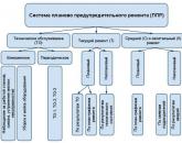
For the repair of complex equipment (computers, power equipment), proprietary service is increasingly used, which is carried out by special divisions of the manufacturer. Currently, the processing enterprises operate a system of scheduled preventive maintenance of equipment (TSHR), which is a progressive form of organization of repair work. PPR is a set of organizational and technical measures aimed at maintaining equipment in working order and preventing its emergency exit from operation. Each machine, after working out a certain number of hours, stops and undergoes preventive inspection or repair, the frequency of which is determined by the design features and operating conditions of the machines. The PPR system at RUE MZIV provides for the following types of service: 1.
Blanker.ru
Table 3.3 Works regulated by the Regulations on PPR for mechanical and electrothermal equipment Name of equipment Types of maintenance and repairs Frequency, months. The number of TO, TP and K in the repair cycle during the service life before decommissioning The structure of the repair cycle Amortization period, years Electric boilers, grills, braziers, autoclaves TO 1 100 5TO… TP-10 TP 6 18 5TO-TP… k 60 1 ... 5TO-IP-K Electric stoves, cabinets, sko TO 1 100 5TO-TP ... 10 breeds, bain-marie TP 6 20 ... 5TO-TP Electric boilers TO 1 50 5TO-TP ... 5 TP 6 8 ... 5TO-TP-k 30 1 5TO-TR-K Electric steam boilers TO 1 100 5TO-TP… 10 pairs of TR 6 17 5TO-TR-K 36 2 Potato-cleaning machines TO 1 80 5TO-TP ...
Equipment PPR system
In some industries, I happened to see how they remove an old, unusable bearing and put another old bearing on the assembly, of course, such an attitude to the financing of production will also cause a corresponding return on production.
- The quality of repairs by personnel, with poor-quality performance, breakdowns will be more frequent. In this case, it will be necessary to schedule repairs and equipment maintenance more often.
- Repair planning quality, qualifications of equipment repair organizers. The organizers of equipment repairs in production include a mechanic, and on large production lines, even a completely department of the chief mechanic.
Drawing up a schedule for scheduled preventive maintenance of equipment
It consists in replacing individual worn-out parts, eliminating defects, performing lubrication and fastening operations, etc. Overhaul is a repair carried out to restore the resource of a product with the replacement or restoration of any of its parts. Major and current repairs can be planned and unplanned.
Attention
Planned repairs are being carried out on schedule. Unscheduled repairs are carried out in order to eliminate the consequences of sudden failures and breakdowns. In most cases, commercial equipment undergoes scheduled overhaul. Planned overhaul is not provided for equipment that does not have mechanical wear (for example, thermal) during operation.
All these works are designed to maintain the operability of machines and devices until the next scheduled repair.
The system of scheduled preventive maintenance includes the following types of technical repair and maintenance: weekly maintenance, monthly maintenance, annual scheduled maintenance, Annual scheduled maintenance is carried out in accordance with the annual schedule of equipment maintenance. Scheduling PPR Annual schedule of scheduled preventive maintenance, on the basis of which the need for repair personnel, materials, spare parts, components is determined. It includes each unit subject to major and current repairs.
To draw up an annual preventive maintenance schedule (PPR schedule), we need standards for the frequency of equipment repair.
Very often, such repairs are called equipment maintenance (scheduled preventive maintenance) or equipment maintenance (equipment maintenance).
- Major repairs. PPR of equipment, it is also scheduled preventive maintenance Today we will consider the weekly repair of equipment (PPR or MOT). It is called weekly symbolically, in fact, depending on the specifics of the equipment, repairs can be organized both more often, for example, several times a week (which is very rare), or much less often, for example, once every two weeks. Or maybe once a month (such repairs are much more common).
PPr graph of technological equipment in food production sample
Here you need to partially disassemble the mechanism, replace and restore worn parts. It is performed without removing the mechanism from the foundation. 5. Overhaul, consisting in replacing worn parts and assemblies, checking and adjusting machines and restoring them in accordance with technical conditions.
Overhaul involves complete disassembly of the equipment with removal, if necessary, from the foundation. Inspections, current and major repairs are carried out by special repair personnel with the involvement of service staff. At the heart of the preparation of the PM plan are the standards and structure of the repair cycle.
The repair cycle is the operating time of the machine from the beginning of its commissioning to the first major overhaul. It depends on the durability of the parts and the operating conditions of the equipment.
These data can be found in the manufacturer's passport data, if the plant specifically regulates this, or use the reference book "Maintenance and repair system". There is a certain amount of equipment. All this equipment must be included in the PPR schedule. Column 1 indicates the name of the equipment, as a rule, concise and understandable information about the equipment.
In column 2 - the number of equipment In column 3-4 - the resource standards between major repairs and current ones are indicated. (See Appendix 2) Columns 5-6 - the labor intensity of one repair (see Table 2 Appendix 3) based on the list of defects. In columns 7-8 - the dates of the last major and current repairs are indicated (conditionally, we take the month of January of the current year) In columns 9-20, each of which corresponds to one month, the symbol indicates the type of planned repair: K - major, T - current.
Info
For the efficient operation of equipment at RUE MZIV, a clear organization of its material and technical maintenance is necessary. A large number of this is assigned to the organization of equipment repair. The essence of the repair is to preserve and restore the performance of equipment and mechanisms by replacing or restoring worn parts and adjusting mechanisms.
Important
Annually more than 10-12% of equipment undergoes major overhaul, 20-30% - medium and 90-100% - small. The cost of repair and maintenance of equipment is more than 10% of the cost of production. Over the entire service life of the machine, the cost of repairing it is several times higher than its original cost.
The main task of the repair facilities is to keep the equipment in a technically sound condition, which ensures its uninterrupted operation.
Number of equipment units 7 2 Number of equipment repairs (inspections) in the structure of the repair cycle · capital 1 1 · average 1 2 · current 2 3 · inspections 20 48 Category of equipment repair complexity 1.5 1.22 Duration of equipment repair, shift · major 1 30 · Average 0.6 18 · current 0.2 8 · inspections 0.1 1 Duration of the repair cycle, months. 18 48 Labor intensity of repairs (inspections) · capital 35.0 35.0 · average 23.5 23.5 · current 6.1 6.1 · inspections 0.85 0.85 on the basis of the "Regulations on the system of preventive maintenance of equipment): for equipment for bottling wines - 100 and other technological equipment 150 conventional repair units. 5.
Equipment that does not meet at least one of the requirements established by operational documentation, standards (GOST), technical conditions (TU) is considered to be faulty. Malfunctions include a decrease in the productivity and economy of machines, loss of accuracy, deviations in technological processes (beyond the permissible limits). The reliability of the equipment is determined by the reliability, durability, maintainability and preservation.
Reliability is the property of equipment to remain operational for a certain operating time, that is, work without failure for a given period of time. Durability reflects such a property of the equipment as maintaining operability until major overhaul or decommissioning. Maintainability is the ability of equipment to prevent, detect, and eliminate failures and malfunctions.
Search in text
Acting
Effective date: "__" ___________ 2016 *
________________
* The text of the document corresponds to the original. -
Database manufacturer's note.
FOR THE FIRST TIME
annotation
annotation
"Recommendations on the procedure and rules for the development, coordination and approval of projects for the production of work with the use of lifting structures" (hereinafter the Recommendations), were developed by a specialist of Stronex LLC (A.E. Savalov) and Inzhstroyproekt LLC (I.E. Videnin) on on the basis of the terms of reference approved by the General Director of the Chelyabinsk Interregional Union of Builders on 05/10/2016.
1 area of use
Adoption of a unified approach of construction organizations to the composition and content of work projects with the use of lifting structures developed during construction, reconstruction, overhaul of capital construction facilities, both for the entire facility as a whole, and for a separate stage (type) of work;
Providing in projects for the production of work descriptions of the technological sequence of work, ensuring a certain level of quality of work, using modern means of mechanization for the production of work.
2. Normative references
- "Rules for labor protection during loading and unloading and placement of goods"; Order of the Ministry of Labor and Social Protection of the Russian Federation N 642n of September 17, 2013; *
________________
* The text of the document corresponds to the original. Repeat, see above. - Note from the manufacturer of the database.
Operational quality control schemes.
Note - When using these recommendations, it is advisable to check the effect of reference normative documents in the public information system - on the official websites of Rostekhregulirovanie, the Ministry of Construction of the Russian Federation, Rostekhnadzor, NOSTROY, SSK UrSib, on the Internet or according to the annually published information index "National Standards", which is published under as of January 01 of the current year, or according to the corresponding monthly published information signs published in the current year. If the reference normative document is replaced (changed), then when using this standard, one should be guided by the replaced (amended) normative document. If the referenced normative document is canceled without replacement, then the provision in which the link to it is given applies in the part that does not affect this link.
3. Terms, definitions and abbreviations
|
Capital construction object- building, structure, structure, objects, the construction of which is not completed, with the exception of temporary buildings, kiosks, sheds and other similar structures Developer- an individual or legal entity providing construction, reconstruction, overhaul of capital construction projects on the land plot that belongs to him, as well as the performance of engineering surveys, preparation of design documentation for their construction, reconstruction, overhaul |
|
Technical customer- an individual acting on a professional basis, or a legal entity who are authorized by the developer and on behalf of the developer conclude contracts for the performance of engineering surveys, on the preparation of project documentation, on construction, reconstruction, overhaul of capital construction projects, prepare tasks for the performance of these types of work , provide the persons performing engineering surveys and (or) preparing design documentation, construction, reconstruction, overhaul of capital construction facilities, materials and documents required to perform these types of work, approve the project documentation, sign the documents required to obtain a permit to enter capital construction object into operation, carry out other functions provided for by this Code. The developer has the right to perform the functions of a technical customer independently. |
|
Person carrying out the construction- the developer or an individual entrepreneur or legal entity engaged by the developer or technical customer on the basis of an agreement, which organizes and coordinates the construction, reconstruction, overhaul of a capital construction facility, ensures compliance with the requirements of project documentation, technical regulations, safety measures in the process of performing these works, and is responsible for the quality of the work performed and their compliance with the requirements of the design documentation. |
Work production project (hereinafter PPR)- a document related to organizational and technological documentation, which contains decisions on the organization of construction production, technology, quality control and safety of the work performed.
Area of possible movement of cargo- the border of the service area of the crane, which is determined by the maximum reach in the parking lot (section between the extreme parking lots) of the crane.
Service area (working area) by crane- zone of movement of goods from storage sites to places of installation and fastening of elements.
Dangerous zone- the area arising from the cargo moved by the crane.
GOST is an interstate standard;
GOST R is the national standard of the Russian Federation;
RD - guiding document;
ФЗ - federal law;
SNiP - building codes and regulations;
SP - a set of rules;
MDS - methodological documentation in construction;
VSN - departmental building codes;
STO - organization standard;
POS - construction organization project;
ITR - engineering and technical workers;
MSK SRF - local coordinate system of the constituent entity of the Russian Federation;
PS - lifting structures;
PPE - Personal Protective Equipment.
4. Requirements for specialists involved in the development of PPR
4.1 PPR is developed by the organization carrying out the construction, in accordance with clause 4.6 of SP 48.13330 "Organization of construction" by specialists trained and certified in the field of industrial safety, in accordance with clause 1.3, RD-11-06.
4.2 Certification of specialists
Initial certification specialists are carried out:
Upon appointment to a position;
When transferring to another job, if certification is required in the performance of official duties at this job.
Periodic certification specialists are held at least once every five years, unless other terms are provided for by other regulatory enactments.
Extraordinary check knowledge of regulatory legal acts and regulatory and technical documents that establish safety requirements on issues related to the competence of a specialist is carried out after the entry into force of new regulatory legal acts and regulatory and technical documents.
The results of knowledge tests on safety issues should be documented in a protocol with the subsequent issuance of a certificate of attestation. The results of the extraordinary certification are documented in a protocol.
4.3 The procedure for passing the certification of specialists should take place in the following sequence:
a) Determination of the place of training of a specialist. Training (education) of specialists should be carried out in organizations licensed for this type of activity;
b) The choice of areas of certification of a specialist in accordance with the type of work performed by the construction organization.
As an example, below are the areas of certification of specialists who develop PPR for construction, reconstruction, overhaul of capital construction objects:
Attestation area А.1 "General industrial safety requirements" - Mandatory area of certification, for all types of activities;
Attestation area B.9.31 "Industrial safety requirements when using lifting structures" - Recommended area of attestation, which is necessary when developing PPR using lifting structures designed for lifting and moving loads;
Attestation area B.9.32 "Industrial safety requirements for lifting structures" - Recommended area of attestation, which is necessary in the development of PPR with the use of lifting structures designed for lifting and transporting people.
Note- When developing PPR during construction at chemical, oil, gas, mining or metallurgical facilities, specialists developing PPR must be certified according to special industrial safety requirements.
c) Submission of documents for attestation to the Rostekhnadzor department.
d) Certification of specialists and receipt of documents in accordance with clause 4.2 of these Recommendations.
5. The procedure for the development, coordination and approval of the PPR
5.3 The composition of the initial data for the development of the PPR must comply with clause 5.7.6. SP 48.13330
5.4 The developed PPR is approved by the person carrying out the construction in accordance with clause 5.7.3 of SP 48.13330 and agreed by the developer (technical customer) or their authorized representatives.
6. The volume and content of PPR
PPR should include text and graphic parts. The scope and content of PPR is considered on the example of the construction of a conditional facility.
Example of a cover page
|
Name of company carrying out construction |
|||||||||||||||
|
Agreed: |
I approve: |
||||||||||||||
|
Developer (Technical customer) |
Representative of the person carrying out the construction |
||||||||||||||
|
PROJECT OF WORK PRODUCTION N PPR Name of works AN OBJECT: "Object name". |
|||||||||||||||
|
Developed by: |
|||||||||||||||
|
Engineer LLC "Organization |
|||||||||||||||
|
Ud. N 00000001 dated 01.01.20 Ud. N 00000002 dated 01.01.20 |
|||||||||||||||
|
City, year |
|||||||||||||||
Layout of geodetic marks (Scheme of geodetic alignment base);
Transport scheme;
Building master plan;
Technological maps for the performance of types of work;
Slinging schemes;
Warehousing schemes;
Clarifying drawings (equipment, protective fences, etc.);
Drawings related to the safety of work;
Schedule for the production of work on the object with a schedule for the receipt of building structures, products, materials and equipment at the object, a schedule for the movement of workers around the facility, a schedule for the movement of the main construction machines at the facility.
6.1.1 Layout of geodetic marks (Layout of geodetic alignment base)
1. The layout of geodetic marks (Scheme of a geodetic grid base) must be transferred by the customer (technical customer) to the person carrying out the construction at least 10 days before the start of construction, together with the act of transferring the geodetic grid base.
2. A geodetic alignment base for construction is created with reference to the points of state geodetic networks available in the construction area or to points of networks that have coordinates and elevations in coordinate systems of the constituent entities of the Russian Federation, on the scale of the general plan of the construction site.
3. The layout of the geodetic alignment base should include:
Construction site center network signs;
Axial marks of the external alignment network of the building (at least 4 per building)
Temporary axle marks;
Coordinate catalog of all points of the geodetic alignment base in the MSK-SRF system
The axis of the building (structure);
The layout of the building on the ground.
An example of a layout of geodetic marks is presented in Appendix A
6.1.2 Transport scheme
1. The transport scheme must be developed for any construction and agreed with the traffic police if the existing transport infrastructure falls within the boundaries of the construction site zone or in the right-of-way of linear structures.
To review and agree on the transport scheme with the inspector, it is necessary to prepare a letter in the form of Appendix B.
2. The transport diagram must show:
The territory of the construction site;
Construction object and on-site warehouses;
Construction camp;
Intrasite temporary roads;
Access roads to the construction site;
Direction of traffic to the construction site;
Direction of traffic on the territory of the construction site;
The direction of movement of pedestrians;
Temporary traffic signs.
3. The transport scheme is signed:
The manager of the organization carrying out the construction.
The manufacturer of the work;
The developer of the transport scheme (engineer for the development of PPR);
Inspector of the traffic police.
An example of a transport scheme is given in Appendix B.
6.1.3 Building master plan
Stroygenplan includes:
Designed and existing buildings and structures;
The boundaries of the construction site and the type of its fence;
Permanent and temporary roads;
Parking spaces under unloading;
Direction of movement of vehicles and mechanisms;
Premises for sanitary and consumer services (construction camp);
Smoking areas;
Places of devices for the removal of construction waste and household waste;
Wheel washing points;
Places of substation installation;
Storage areas for building materials;
Large-scale assembly sites (if any);
The boundaries of the zones formed during the operation of the substation;
Ways and means of lifting (lowering) workers to the place of work;
Placement of power supply and lighting sources;
Operating underground, overhead and air communications;
Location of grounding loops.
6.1.3.1 Designed and existing buildings and structures
It is advisable to start the development of a construction plan with drawing the designed, as well as existing buildings and structures, within the boundaries of the improvement (red lines), see Fig. 1.
Fig. 1. Designed and existing buildings within the boundaries of the improvement
Fig. 1. Designed and existing buildings within the boundaries of the improvement
6.1.3.2 Site boundaries
1. The construction site fencing should be installed along the border of the territory improvement.
2. Select the type of fencing for the construction site in accordance with clause 2.2 of GOST 23407 "Inventory fencing of construction sites and construction and installation work areas. Specifications".
Types of security fences for construction sites are given in Appendix D.
3. In places where the dangerous zone during the operation of the substation goes beyond the territory of the construction site, the protective and security fence should be made with a visor.
4. In places where pedestrians pass, sidewalks with a protective canopy should be made, see Fig. 2. Requirements for the construction of a pedestrian walkway and a protective visor are given in clauses 2.2.5-2.2.13, GOST 23407.
Fig. 2. Diagram of the protective visor device
Diagram of the protective visor device
|
1 - fence post; 2 - fencing panel; 3 - support (bed), step 1.0 m (board t = 50 mm) 4 - sidewalk panel (board t = 50 mm); 5 - horizontal element of the railing (board t - 25 mm); 6 - handrail post (beam 100x100 mm), step 1.5 m; 7 - canopy rafter (board t = 50x100 mm), pitch 1.5 m; 8 - visor panel (profiled sheet); 9 - canopy strut (board t = 50x100 mm), step 1.5 m; 10 - panel brace (board t = 50x100 mm), step 1.5 m; 11 - protective screen (when laying a pedestrian sidewalk along highways) |
|
|
Fig. 2. Diagram of the protective visor device |
|
The symbols indicated on the construction master plans are given in Appendix D.
5. It is advisable to enter the construction site from the existing public roads.
When entering the construction site, the following must be installed:
Checkpoint;
From the side of the street there is an information board, a transport scheme and road signs in accordance with GOST R 52290-2004 - N 3.2 "No traffic" and N 3.24 "speed limit 5 km / h"; sign "entry".
The information board indicates the name of the object, the name of the developer (Customer), the general contractor (technical customer), the name, position and phone numbers of the responsible manufacturer of work on the object, the start and end dates of work, the scheme of the object (clause 6.2.8 SP 48.13330.2011 "Organization of construction"), see Fig. 3.
Fig. 3. An example of a bulletin board for a construction site
Fig. 3. An example of a bulletin board for a construction site
The construction site with an area of 5 hectares or more must be equipped with at least 2 exits arranged from opposite sides, in accordance with clause 8.24 of RD-11-06.
It is advisable to leave the territory of the construction site on the existing public roads. At the exit from the territory (if possible), establish a checkpoint and post the necessary road signs in accordance with GOST R 52290:
Sign N 2.4 "Give way" (sign N 2.5 "Driving without stopping is prohibited");
Sign N 4.1.1 "Driving straight", sign N 4.1.2 "Driving right", sign N 4.1.3 "Driving left", sign N 4.1.4 "Driving straight or right", sign N 4.1.5 "Driving straight or to the left ", sign N 4.1.6" Movement to the right or to the left "- (according to the situation);
Exit sign.
Fig. 4. Construction site fencing scheme
Fig. 4. Construction site fencing scheme
6.1.3.3 On-site temporary roads
1. Intra-building roads should provide access to the area of operation of assembly cranes, to pre-assembly sites, warehouses, mobile (inventory) buildings
The following dimensions must be applied to the construction plan:
The width of the roads;
Turning radii.
2. It is advisable to take the width of the on-site roads in accordance with clause 8.17 of RD 11-06-2007:
For single-lane traffic - 3.5 m;
With two-lane traffic - 6.0 m.
When using vehicles with a carrying capacity of 25 tons or more, the width of the carriageway must be increased to 8.0 m.
In places of curvature, the width of a single-lane road should be increased by 5.0 m.
Note:
When designing roads for the installation of self-propelled jib cranes, the width of temporary roads should be taken 0.5 m more than the width of the caterpillar or wheel travel of the crane used in accordance with clause 8.18, RD 11-06, see Fig. 5.
Fig. 5. Temporary road under the self-propelled jib crane
Fig. 5. Temporary road under the self-propelled jib crane
3. When tracing roads, the following minimum distances must be observed:
From the edge of the roadbed and the storage area - 0.5-1.0 m;
From the edge of the roadbed and the fence of the tower crane and the construction site - 1.5 m;
From the edge of the roadbed and the edge of the trench - in accordance with the distances indicated in table 1 of SP 49.13330 + 0.5 m.
4. The thickness and construction of the pavement of temporary on-site roads should be determined in the PIC.
The thickness of the pavement of temporary on-site roads is recommended to be taken depending on the type of pavement material. The types of temporary road coverage are given below:
Crushed stone (gravel) - 400 mm;
From monolithic concrete with a thickness of 170-250 mm on sand preparation with a thickness of 250 mm;
From precast reinforced concrete slabs 170-200 mm thick on sand (crushed stone) preparation with a thickness of 100 mm.
4. Type of on-site roads:
With circular traffic, fig. 6a. The rounding radii of the roads depend on the vehicles delivering the goods and are accepted from 9.0 to 18.0 m;
Fig.6a. Stroygenplan with a ring road inside the site
Fig.6a. Stroygenplan with a ring road inside the site
Dead-end, with turning platforms, see Fig. 6b;
Fig. 6b. Construction plan with dead-end roads
Fig. 6b. Construction plan with dead-end roads
Through, with a separate exit from the construction site to public roads, see Fig. 6c.
Fig. 6c. Stroygenplan with the second exit
6.1.3.4 Transport parking spaces for unloading (loading) materials
1. The dimensions of the parking lots for unloading (loading) should be taken on the basis of the following dimensions:
Parking width - 3.0 m;
The length of the camps is at least 15.0 m.
2. Places for parking vehicles for unloading / loading arrange along the main temporary roads in the working area of cranes, see Fig. 7.
Fig. 7. Stroygen plan with marked parking lots for unloading / loading
Fig. 7. Stroygen plan with marked parking lots for unloading / loading
3. After defining the scheme of on-site roads and parking lots, show the direction of traffic on the construction site, see Fig. 8.
Fig. 8. The scheme of the direction of traffic on the construction site
Fig. 8. The scheme of the direction of traffic on the construction site
6.1.3.5 Premises for sanitary services (construction camp)
1. On the territory of the construction site, premises for sanitary and household services for workers (construction camp), as well as security posts at the entrance and exit from the territory of the construction site, must be located in compliance with the following conditions:
Place the site for the placement of sanitary facilities on a flood-free area, on a prepared base and equip it with drainage drains.
As a base, it is recommended to take a crushed stone base with a thickness of 250 mm, see Fig. 9a or a base made of reinforced concrete slabs with a thickness of 170 mm on a sandy base with a thickness of 100 mm, see Fig. 9b
Fig. 9a. Crushed stone base 250 mm thick
Fig. 9b. The base is made of reinforced concrete slabs
Fig. 9b. The base is made of reinforced concrete slabs
It is advisable to place sanitary facilities in special buildings of a collapsible or mobile type outside the * hazardous areas. It is possible to use separate rooms in existing buildings and structures for construction needs. When using existing buildings and structures, the requirements of clause 6.6.3 of SP 48.13330 must be observed;
___________________
* The text of the document corresponds to the original. - Note from the manufacturer of the database.
Sanitary facilities should be removed from the place of unloading devices at a distance of at least 50 m in accordance with clause 12.7 of SanPiN 2.2.3.1384-03. At a distance of no more than 150 m from the place of work, premises for heating workers and toilets should be installed, the calculation of which should be performed in the POS.
If it is necessary to use the territories not included in the construction site for the placement of temporary buildings and structures, follow clause 6.6.2 of SP 48.13330.
2. It is advisable to equip the construction site with smoking areas at a distance of at least 10 m from sanitary facilities. Smoking areas must be equipped with primary fire extinguishing equipment in accordance with the "Fire Fighting Regulations in the Russian Federation". Mark the smoking areas on the construction plan with a cross.
Symbols are given in Appendix D.
Fig. 10. Placement of sanitary facilities
6.1.3.6. Debris and household waste disposal facilities
The construction site must be equipped with containers for the disposal of construction waste and household waste, see fig. 11. It is advisable to place containers for household waste at the entrance and exit from the construction site. It is advisable to place containers for construction waste in the immediate vicinity of the construction site.
Containers for construction waste should be metal, containers for household waste - plastic or metal.
Fig. 11. Equipping a construction site with containers for construction and household waste
Fig. 11. Equipping a construction site with containers for construction and household waste
6.1.3.7 Cleaning point (washing)
The composition of the point for cleaning (washing) wheels:
Base plates with drainage to a drainage well;
Washing complex;
Installation for cleaning wheels with compressed air (in winter).
Fig. 12. Types of wheel washing points
Fig. 12. Types of wheel washing points. A) in the form of platforms; B) in the form of overpasses
1 - washing complex; 2 - drainage well; 3 - pipe d200-300 mm; 4 - channel N 30 (half-pipe d300); 5 - road slabs PAG-XIV
Variants of placement of a complex of equipment for a wheel washing station, Fig. 13.
Fig. 13. Variants of placement of a complex of equipment for a wheel washing station
Fig. 13. a, b, c) - with single-lane traffic, d, e) - with double-lane traffic and combining entry and exit
The point for cleaning (washing) the wheels of trucks and construction machines should be installed at the exit from the construction site, see Fig. 14.
Fig. 14. Layout of a wheel washing station on a construction site
Fig. 14. Layout of a wheel washing station on a construction site
6.1.3.8 Substation locations
1. It is advisable to start the substation installation on the construction plan by determining the substation installation site, see Fig. 15.
Regardless of the type, the substation should be installed on a planned and prepared site in the immediate vicinity of the construction site, subject to the following conditions:
Compliance of the installed lifting structures (hereinafter referred to as SS) to the conditions of construction and installation works in terms of carrying capacity, lifting height and reach (load characteristics of the SS);
Ensuring a safe distance from networks and overhead power lines (see table 2 of SP 49.13330), places of movement of urban transport and pedestrians, as well as safe distances for the substation to approach buildings and places of storage of construction parts and materials, (see paragraphs 101-137 of the Rules safety of hazardous production facilities where lifting structures are used);
Compliance with the installation and operation conditions of the substation near the slopes of the pits should be performed in accordance with table No. 1 of SP 49.13330;
Compliance with the conditions for the safe operation of several substations and other equipment (mechanisms) simultaneously located at the construction site (if any);
Compliance with the conditions of the places of installation of lifting structures in the places of passage of underground utilities.
Fig. 15. Tower crane installation site
The minimum distance from the boom of the crane or the hoist (tower) during operation to the wires of the power line, which are energized
Table 1
|
Overhead line voltage, kW |
The smallest distance, m |
|
1 to 20 |
|
|
35 to 100 |
|
|
150 to 220 |
|
|
500 to 750 |
|
|
750 to 1150 |
|
|
800 (DC) |
Compliance with the conditions of installation and operation of the substation near the slopes of the pits according to table N 2.
table 2
Horizontal distance from the base of the slope of the excavation to the nearest support of the machine, m
|
Pit depth, m |
|||||
|
Sandy and gravel |
sandy loam |
loamy |
Loess |
clayey |
|
Fig. 16. Installation diagram of the crane near the slope of the excavation
An example of the selection of a lifting crane
The selection of cranes is carried out according to three main parameters:
- required lifting capacity.
When choosing a lifting crane for construction and installation work, it is necessary to ensure that the weight of the load being lifted, taking into account the lifting devices and containers, does not exceed the permissible (passport) lifting capacity of the lifting crane. To do this, it is necessary to take into account the maximum weight of the mounted products and the need to feed them by a crane for installation to the most distant design position, taking into account the permissible lifting capacity of the crane at a given boom outreach;
Required lifting capacity of the crane, t;
Weight of the lifted load, t (bunker with concrete mix - 2.7 t);
Weight of the load-gripping device, tn (sling 0.05 tn);
Weight of attachments, tn (none);
The mass of structures for reinforcing the rigidity of the load being lifted, t. (there are none)
2.7tn + 0.05tn = 2.75tn
- required lifting height;
The crane operator must have an overview of the entire working area. The area of operation of the crane should cover the height, width and length of the building under construction, as well as the area for storing the mounted elements and the road along which the goods are transported.
The required lifting height is determined from the elevation of the installation of the crane vertically and is made up of the following indicators: the height of the building (structure) from the zero elevation of the building, taking into account the elevation of the crane installation to the upper elevation of the building, a headroom of 2.3 m from the conditions of safe work on the upper elevation of the building where people can be, the maximum height of the moved load (in the position in which it is moved), taking into account the mounting devices or reinforcement structures attached to the load, the length (height) of the load-gripping device in the working position.
Height of the upper elevation of the building, m (65.0 m - according to the project)
The difference between the elevation of the parking lot of the cranes and the zero elevation of the building, m (the crane is installed at the level of the bottom of the building's foundation slab - -9.8 m);
Maximum height of the transported cargo, m (3.0 m - the length of the bunker with the concrete mixture);
Length of lifting device (3.5 m - length of lifting device).
= (65.0 m + 9.8 + 3.0 m + 3.5 m + 2.3 m) = 83.6 m
- required boom reach
The required working reach is determined by the horizontal distance from the axis of rotation of the slewing part of the crane to the vertical axis of the load-gripping body (determined graphically), see Fig. 17.
The approach to the building (structure) of the attachment crane is determined by the minimum outreach, which ensures the installation of structural elements of buildings closest to the crane tower, taking into account the dimensions of the crane foundation and the conditions for attaching the crane to the building.
Fig. 17. Boom reach required
Fig. 17. Boom reach required
Based on the obtained values, we select a Liebherr 132ES-H8 crane, lifting capacity 8.0 tn, Lstr = 50.0 m. Maximum lifting height - 85.7 m
Lifting table of Liebherr 132EC-H8 tower crane, lifting capacity 8.0 tons, Lstr = 50.0 m
|
Boom reach |
|||||||||
|
carrying capacity |
|
Boom reach |
|||||||||
|
carrying capacity |
Lifting table of Liebherr 132EC-H8 tower crane, lifting capacity 8.0 tn, Lstr = 50.0 m (continued)
|
Boom reach |
|
|
carrying capacity |
|
Technical specifications |
Required values |
Crane characteristics |
|
Carrying capacity, t |
||
|
Hook outreach, m |
||
|
Hook lifting height, m |
6.1.3.9 Warehouses of building materials and sites for pre-assembly of structures
1. Warehouses of building materials
By design and storage method of materials and products, warehouses are divided into the following types:
Open (storage areas) - for storing materials and products that do not deteriorate under the influence of atmospheric and temperature precipitation and sunlight (prefabricated reinforced concrete structures, metal products, bricks, etc.);
Semi-closed (sheds) - for storing materials that are damaged by direct exposure to atmospheric precipitation and sunlight (roll roofing materials, joinery, etc.);
Closed (containers, booths) - for storing valuable materials, as well as cement, lime, dyes, glass, hardware, etc.).
Place open warehouses at the construction site in the area of possible movement of cargo by a crane serving the facility, see Fig. 18.
The area of possible movement of the load is the space, the boundary of which is a circle described by the crane hook, with a radius equal to the maximum outreach of the crane boom.
Fig. 18. Warehouse layout
Fig. 18. Warehouse layout
Open and semi-closed storage areas should be flat, planned with a slope of no more than 5 ° to drain surface water, cleaned of debris and foreign objects.
The placement of materials and structures in open warehouses should be carried out so that the goods with the largest dimensions are located closest to the hoisting mechanism.
Materials, products and structures during storage in warehouses and workplaces must be stacked in accordance with clause 7 of POT R O 14000-007-98 or in accordance with GOST and STO of the manufacturer of materials, products and structures
An example of storage of sandwich panels according to the TU of the manufacturer
Store the packages of wall sandwich panels stacked in one or several tiers, the total height of which should be no more than 2.4 m, see Fig. 19. Place the bottom package of panels on wooden pads with a thickness of at least 10 cm, and located with a step of not more than 1 meter, providing a slope of 1 ° of the package of panels during storage, for the free flow of condensate. When storing panels packed in boxes, the height of the tiers is not limited
Note:
Provide 1 m wide passages between the stacks. Arrange passages at least every 2 stacks in the longitudinal direction and at least 25 m in the transverse direction.
Fig. 19. Sandwich panels storage scheme
It is prohibited:
Storage of materials and structures outside the storage areas.
It is prohibited to lean (lean) materials and products against fences, trees and elements of temporary and permanent structures.
2. Pre-assembly sites
Large-scale assembly sites are performed if, due to large dimensions or weight, the structure as a whole cannot be delivered to the construction site. As a rule, large-span trusses, crane beams of industrial buildings and tall columns are subject to pre-assembly.
It is also possible to enlarge assembly of structures into blocks (roof structures), as well as to enlarge assembly of flat reinforcing meshes into spatial frames.
, it usually takes no more than a few minutes. spp@cntd.ru, we'll figure it out.
DRAFTING A PREVENTIVE REPAIR SCHEDULE (PPR)
In order to ensure reliable operation of equipment and prevent malfunctions and wear, enterprises periodically carry out scheduled preventive maintenance of equipment (PPR). It allows you to carry out a number of works aimed at restoring equipment, replacing parts, which ensures economical and continuous operation of the equipment.
The alternation and frequency of scheduled preventive maintenance (PPR) of equipment is determined by the purpose of the equipment, its design and repair features, dimensions and operating conditions.
The equipment is stopped for routine maintenance while it is still in working order. This (planned) principle of withdrawing equipment for repair makes it possible to make the necessary preparations for stopping the equipment - both from the side of the service center specialists and from the customer's production personnel. Preparation for scheduled preventive maintenance of equipment consists in clarifying equipment defects, selecting and ordering spare parts and parts that should be replaced during repair.
Such training allows the full scope of repair work to be carried out without disrupting the normal operation of the enterprise.
Competent execution of the PPR involves:
- · Planning of scheduled preventive maintenance of equipment;
- · Preparation of equipment for scheduled preventive maintenance;
- · Carrying out scheduled preventive maintenance of equipment;
- · Carrying out activities related to scheduled preventive maintenance and equipment maintenance.
Routine equipment repair includes the following stages:
1. Overhaul stage of service.
The overhaul stage of equipment maintenance is carried out mainly without interrupting the operation of the equipment itself.
The overhaul phase of equipment maintenance consists of:
- · Systematic cleaning of equipment;
- · Systematic lubrication of equipment;
- · Systematic inspection of equipment;
- · Systematic adjustment of equipment operation;
- · Change of parts with a short service life;
- · Elimination of minor faults and defects.
The overhaul phase of maintenance is prevention in other words. The overhaul phase of maintenance includes daily inspection and maintenance of the equipment and must be properly organized in order to:
- · Dramatically extend the period of operation of the equipment;
- · Maintain excellent quality of work;
- · Reduce and accelerate the costs associated with scheduled maintenance.
The overhaul stage of maintenance consists of:
- · Tracking the condition of the equipment;
- · Carrying out the rules of proper exploitation by the workers;
- · Everyday cleaning and lubrication;
- · Timely elimination of minor breakdowns and regulation of mechanisms.
The overhaul stage of service is carried out without stopping the production process. This stage of maintenance is carried out during interruptions in the operation of the equipment.
2. The current stage of scheduled preventive maintenance.
The current stage of preventive maintenance is often carried out without opening the equipment, temporarily stopping the operation of the equipment. The current stage of preventive maintenance consists in eliminating breakdowns that appear during operation and consists of inspection, lubrication of parts, and equipment cleaning.
The current stage of scheduled preventive maintenance precedes overhaul. At the current stage of preventive maintenance, important tests and measurements are carried out, leading to the identification of equipment flaws at an early stage of their appearance. Having assembled the equipment at the current stage of preventive maintenance, it is adjusted and tested.
The decision on the suitability of the equipment for further work is made by the repairmen, based on a comparison of the test results at the current stage of scheduled preventive maintenance with the existing standards, the results of past tests. Equipment that cannot be transported is tested using electrotechnical mobile laboratories.
In addition to scheduled preventive maintenance, work is carried out outside the plan to eliminate any flaws in the operation of the equipment. These works are carried out after the entire working resource of the equipment has been exhausted. Also, to eliminate the consequences of accidents, emergency recovery repairs are carried out, which requires the immediate termination of equipment operation.
3. The middle stage of scheduled preventive maintenance
The middle stage of preventive maintenance is intended for partial or complete restoration of used equipment.
The middle stage of preventive maintenance is to disassemble equipment components for viewing, cleaning parts and eliminating identified flaws, changing parts and assemblies that wear out quickly and which do not ensure proper use of the equipment until the next major overhaul. The middle stage of scheduled preventive maintenance is carried out no more than once a year.
The middle stage of preventive maintenance includes repairs, in which the normative and technical documentation establishes the cyclicality, volume and sequence of repair work, even regardless of the technical condition in which the equipment is located.
The middle stage of preventive maintenance affects the fact that the equipment is maintained normally, there is little chance that the equipment will fail.
4. Overhaul
Overhaul of the equipment is carried out by opening the equipment, checking the equipment with a meticulous inspection of the "insides", testing, measurements, elimination of identified breakdowns, as a result of which the equipment is being modernized. Overhaul provides restoration of the original technical characteristics of the equipment.
Overhaul of the equipment is carried out only after the overhaul period. For its implementation, it is necessary to carry out the following steps:
- · Scheduling of work performance;
- · Carrying out preliminary inspection and verification;
- · Preparation of documentation;
- · Preparation of tools, spare parts;
- · Implementation of fire-prevention and safety measures.
Equipment overhaul consists of:
- · In replacement or restoration of worn-out parts;
- · Modernization of any parts;
- · Performing preventive measurements and checks;
- · Carrying out works on elimination of minor damages.
Defects that are discovered during the inspection of the equipment are eliminated during the subsequent overhaul of the equipment. Breakdowns that are of an emergency nature are eliminated immediately.
The specific type of equipment has its own frequency of scheduled preventive maintenance, which is regulated by the rules of technical operation.
Measures under the SPR system are reflected in the relevant documentation, with strict consideration of the availability of equipment, its condition and movement. The list of documents includes:
- · Technical data sheet for each mechanism or its duplicate.
- · Equipment accounting card (annex to the technical passport).
- · Annual cyclical equipment repair schedule.
- · Annual plan-estimate of equipment overhaul.
- · Monthly plan-report of equipment repair.
- · Acceptance certificate for overhaul.
- · Replaceable log of malfunctions of technological equipment.
- · Extract from the annual PPR schedule.
On the basis of the approved annual PM schedule, a nomenclature plan for the production of capital and current repairs is drawn up, broken down by months and quarters. Before the start of major or current repairs, it is necessary to clarify the date of setting the equipment for repair.
The annual PPR schedule and tables of initial data are the basis for drawing up an annual budget plan, which is developed twice a year. The annual amount of the plan-estimate is divided by quarters and months, depending on the period of capital repairs according to the PPR schedule of the given year.
Based on the plan-report, the accounting department is provided with a report on the costs incurred for capital repairs, and the manager is provided with a report on the implementation of the nomenclature repair plan according to the annual maintenance schedule.
Currently, for scheduled preventive maintenance (PM), computer and microprocessor equipment (installations, stands, devices for diagnostics and testing of electrical equipment) are increasingly used, which affect the prevention of equipment wear and reduce the time of equipment repair, reduce repair costs, and improves the efficiency of electrical equipment operation.
The system of scheduled preventive maintenance or the system of PPR, as it is customary to abbreviate this method of organizing repairs, is a fairly common method that originated and became widespread in the countries of the former USSR. The peculiarity of such "popularity" of this type of organization of the repair economy was that it fit quite harmoniously into the planned form of economic management of that time.
Now let's figure out what a PPR (scheduled preventive maintenance) is.
System of scheduled preventive maintenance (PPR) equipment- a system of technical and organizational measures aimed at maintaining and (or) restoring the operational properties of technological equipment and devices as a whole and (or) individual pieces of equipment, structural units and elements.
Enterprises use various types of preventive maintenance (PPR) systems. The main similarity in their organization is that the regulation of repair work, their frequency, duration, cost of these work is planned. However, various indicators serve as indicators for determining the timing of scheduled repairs.
PPR classification
I would single out several varieties of the preventive maintenance system, which have the following classification:
regulated PPR (scheduled preventive maintenance)
- PPR by calendar periods
- PPR by calendar periods with adjustment of the scope of work
- PPR for operating time
- PPR with regulated control
- PPR by operating modes
PPR (scheduled preventive maintenance) as:
- PPR for the permissible level of the parameter
- PPR for the permissible level of the parameter with the correction of the diagnostic plan
- PPR for the permissible level of the parameter with its prediction
- PPR with control of the level of reliability
- PPR with a forecast of the level of reliability
In practice, the system of scheduled preventive maintenance (PPR) is widespread. This can be explained by its greater simplicity in comparison with the SPR system by state. In the regulated PPR, the binding goes to calendar dates and it is simplified to accept the fact that the equipment operates throughout the entire shift without stopping. In this case, the structure of the repair cycle is more symmetrical and has fewer phase shifts. In the case of organizing the PPR system according to any permissible indicator parameter, it is necessary to take into account a large number of these indicators, specific for each class and type of equipment.
Benefits of using a PPR system or preventive maintenance of equipment
The system of scheduled preventive maintenance of equipment (PPR) has a large number of advantages that determine its widespread use in industry. As the main ones, I would single out the following advantages of the system:
- control of the duration of the overhaul periods of the equipment
- regulation of equipment downtime for repair
- forecasting the cost of repairing equipment, assemblies and mechanisms
- analysis of the causes of equipment breakdown
- calculation of the number of repair personnel depending on the complexity of the equipment
Disadvantages of the PPR system or scheduled preventive maintenance of equipment
Along with the visible advantages, there are a number of disadvantages of the SPR system. I will make a reservation in advance that they are mainly applicable to enterprises of the CIS countries.
- lack of convenient tools for planning repairs
- labor intensity of labor costs calculations
- laboriousness of accounting parameter-indicator
- the complexity of the operational adjustment of planned repairs
The above-mentioned shortcomings of the PPR system relate to a certain specificity of the technological equipment park installed at the CIS enterprises. First of all, this is a high degree of equipment wear. Equipment wear often reaches 80 - 95%. This significantly deforms the system of scheduled preventive maintenance, forcing specialists to adjust the maintenance schedule and perform a large number of unplanned (emergency) repairs, significantly exceeding the normal volume of repair work. Also, when using the method of organizing the PPR system by operating time (after a certain time of equipment operation), the labor intensity of the system increases. In this case, it is necessary to organize accounting of actually worked machine hours, which, together with a large fleet of equipment (hundreds and thousands of units), makes this work impossible.
The structure of repair work in the PPR system of equipment (scheduled preventive maintenance)
The structure of repair work in the PPR system of equipment is determined by the requirements of GOST 18322-78 and GOST 28.001-78

Despite the fact that the PPR system assumes a trouble-free model of equipment operation and repair, in practice it is necessary to take into account unscheduled repairs as well. Their cause is most often an unsatisfactory technical condition or an accident due to poor quality
2. System for preventive maintenance of equipment
The planned preventive form of organizing the repair of technological equipment throughout the world is recognized as the most effective and is most widely used. The development of a system for preventive maintenance of equipment began in the USSR in 1923. At present, various versions of the PM system are the basis for organizing maintenance and repair of equipment at enterprises in most branches of the sphere of material production and service.
System for preventive maintenance of equipment is a set of planned organizational and technical measures for the care, supervision of equipment, its maintenance and repair. The purpose of these measures is to prevent progressively increasing wear, prevent accidents and keep equipment in constant readiness for operation. The PPR system involves the implementation of preventive measures for the maintenance and scheduled repair of equipment after a certain number of hours of its operation, while the alternation and frequency of measures are determined by the characteristics of the equipment and the conditions of its operation.
PPR system includes
Maintenance
and scheduled equipment repair.
Maintenance- is a set of operations to maintain the performance of equipment when using it for its intended purpose, during storage and transportation. Maintenance includes
routine overhaul
and periodic preventive maintenance operations.
Routine overhaul service consists in the daily monitoring of the condition of the equipment and compliance with the rules of its operation, the timely regulation of mechanisms and the elimination of minor malfunctions that arise. These works are performed by the main workers and maintenance personnel on duty (locksmiths, lubricators, electricians), as a rule, without equipment downtime. Periodic preventive maintenance operations are regulated and carried out by repair personnel according to a pre-developed schedule without equipment downtime. These operations include
inspections carried out to identify defects that must be eliminated immediately or at the next scheduled repair;
flushing and oil change, provided for equipment with a centralized and crankcase lubrication system;
accuracy check carried out by the technical control staff and the chief mechanic.
Planned repairs includes
Maintenance
and major repairs.
Maintenance is carried out during the operation of the equipment in order to ensure its operability until the next scheduled repair (the next current or major). Routine repair consists in replacing or restoring individual parts (parts, assembly units) of equipment and adjusting its mechanisms. Overhaul carried out in order to restore the full or close to full service life of the equipment (accuracy, power, productivity). Overhaul, as a rule, requires repair work in stationary conditions and the use of special technological equipment. Therefore, it is usually required to remove equipment from the foundation at the site of operation and deliver it to a specialized department where overhaul is carried out. During a major overhaul, the equipment is completely disassembled with checking all its parts, replacing and restoring worn parts, reconciling coordinates, etc.
The repair and maintenance system, depending on the nature and operating conditions of the equipment, can function in different organizational forms:
in the form of a post-examination system,
periodic maintenance systems
or a standard repair system.
Post inspection system involves carrying out inspections of the equipment according to a pre-developed schedule, during which its condition is established and a list of defects is drawn up. Based on the inspection data, the timing and content of the upcoming repair are determined. This system is applicable to some types of equipment operating under stable conditions.
Periodic repair system involves planning the timing and scope of repair work of all types on the basis of a developed regulatory framework. The actual scope of work is adjusted relative to the normative according to the results of the inspection. This system is most common in mechanical engineering.
Standard repair system involves planning the scope and content of repair work on the basis of precisely established standards and strict adherence to repair plans, regardless of the actual condition of the equipment. This system applies to equipment, the unplanned stop of which is unacceptable or dangerous (for example, lifting and transporting devices).
The effectiveness of the PM system is largely determined by the development of its regulatory framework and the accuracy of the established standards. The standards of the PPR system of the enterprise are differentiated by equipment groups. Main repair standards are
repair cycles and their structure,
labor intensity and material consumption of repair work,
inventory for repair needs.
Repair cycle- this is the period of time from the moment the equipment is put into operation until the first overhaul or between two successive overhauls. The repair cycle is the smallest repetitive period of equipment operation, during which all types of maintenance and repair are carried out in the established sequence in accordance with the structure of the repair cycle. The structure of the repair cycle establishes the list, quantity and sequence of equipment repairs during the repair cycle. For example, a repair cycle structure might include the following repair sequence:
K - T 1 - T 2 - T 3 - TO,
where T 1 , T 2 and T 3 - respectively, the first, second and third current repairs;
TO- overhaul (only one overhaul is included in the repair cycle).
The content of work performed as part of each of the current repairs is regulated and may differ significantly from others present in the repair cycle. In the structure of the repair cycle, a small ( M) and average ( WITH) repair: for example, T 2 = C; T 1 = T 3 = M.
Similarly, the structure of the maintenance cycle can be presented, establishing the list, number and sequence of overhaul maintenance work (shift inspection, partial inspection, lubrication replenishment, lubricant change, preventive adjustment, etc.). It is possible to include maintenance work ( THEN) into the structure of the repair cycle, for example:
WHO 1 - T 1 - THEN 2 - T 2 - THEN 3 - T 3 - THEN 4 - TO.
The repair cycle is measured by the operational time of the equipment, the downtime in repair is not included in the cycle. The duration of the repair cycle is determined by the service life of the main mechanisms and parts, the replacement or repair of which can be carried out during the complete disassembly of the equipment. Wear of main parts depends on many factors, the main of which are
the type of production on which the intensity of the use of equipment depends;
physical and mechanical properties of the processed material, on which the intensity of wear of equipment and its parts depends;
operating conditions, such as high humidity, dustiness and gas pollution;
equipment accuracy class, which determines the level of requirements for monitoring the technical condition of equipment;
Duration of the repair cycle T is determined in the worked machine-hours by a calculation method according to empirical dependencies, taking into account the influence of many factors, including those listed above:
where T n- standard repair cycle, hours (for example, for certain metal-cutting machines T n= 16 800 hours);
ß P , ß m , ß at , ß T , ß R- coefficients, taking into account the type of production, type of processed material, operating conditions, accuracy and dimensions of the equipment, respectively.
The values of the coefficients and the standard duration of the repair cycle are determined on the basis of generalization and analysis of the actual data of the enterprise or are taken according to reference data.
Overhaul period T mr and maintenance intervals T then are also expressed by the number of hours worked:
 ,
(104)
,
(104)
 ,
(105)
,
(105)
where n T and n THEN- respectively, the number of current repairs and maintenance work per one repair cycle.
The duration of the repair cycle, the overhaul period and the frequency of maintenance can be expressed in years or months, if the shift of the equipment is known. Proper care of equipment during its operation, organizational and technical measures that extend the service life of parts and parts of equipment, contribute to a change in the actual duration of the repair cycle and overhaul periods in comparison with the standard. The service life of wearing parts and equipment parts is shorter than the overhaul period. Therefore, it is advisable to replace them as they wear out during the overhaul period. At the same time, the complexity of the repair is reduced, the volume of work on overhaul maintenance increases.
Labor intensity and material consumption of equipment repair and maintenance depend on its design features. The more complex the equipment, the larger its dimensions and the higher the processing accuracy, the higher the complexity of its repair and maintenance, the higher the labor intensity and material consumption of these works. According to the complexity of the repair, the equipment is divided into categories of repair complexity. The labor intensity of repair work separately for the mechanical and electrical parts of the equipment is determined through the labor intensity of the unit of complexity of repair.
Repair complexity category (TO) is the degree of complexity of equipment repair. The category of equipment repair complexity is determined by the number of units of repair complexity assigned to a given group of equipment by comparing it with the accepted standard - conventional equipment. At domestic mechanical engineering enterprises, the repair complexity of conventional equipment is traditionally taken as a unit of repair complexity of a mechanical part, the labor intensity of which overhaul is 50 hours, for a unit of repair complexity of its electrical part - 12.5 hours (1/11 of the labor intensity of the overhaul of a screw-cutting lathe 1K62, which was assigned the 11th category of repair complexity).
Repair unit (R. e.) is the labor intensity of the corresponding type of equipment repair of the first category of repair complexity. Labor intensity rates for one repair unit are set by type of repair work (flushing, checking, inspection, current and overhaul repairs) separately for locksmith, machine tools and other works. The labor intensity of each type of repair work is determined by multiplying the time norms for a given type of work for one repair unit by the number of repair units of the category of complexity of repair of the corresponding equipment.
Total labor intensity of repair work (Q) in the planning period is calculated by the formula:
q K , q T and q THEN- norms of labor intensity of capital and current repairs, technical maintenance per one repair unit, hours;
n TO , n T , n THEN- the number of major and current repairs, maintenance work in the planned period.


Popular
- Preventive maintenance and its role in production
- Planned preventive maintenance of equipment
- On the procedure for placing non-stationary objects of seasonal trade
- Provisions on the placement of non-stationary shopping facilities
- Decorative painting in kindergarten "magic curl" is a joint activity of the teacher and
- Synopsis of the organization and conduct of classes on cognitive development in the second junior group "Bird feeder
- New professions Where to get information about the right specialists
- Plasticine diplodocus. Sculpting lesson. How to easily make basic shapes from plasticine: a ball, cone, cylinder, plait, brick How to make a cylinder from plasticine
- Rating of recruiting agencies
- Rating of recruiting agencies