Electronic cube diagram. Radio circuits electrical schematic diagrams
The construction, the description of which is presented below, performs the functions of a game cube, but has the advantage over it that it does not require throwing a real cube on a horizontal surface. The basis of the device is an indicator consisting of seven LEDs HL1-HL7 (Fig. 1), located so as to highlight the configuration of any of the six sides of the cube.
In accordance with the structural diagram (Fig. 2), the device contains a pulse generator, a counter, a code converter (decoder) and the aforementioned LED indicator.

The schematic diagram of the device is shown in Fig. 3. A pulse generator is assembled on the elements DD1.1- DD1.3 of the DD1 microcircuit according to the standard scheme. The pulses are fed to the input C2 (pin 1) of the counter made on the DD2 microcircuit. Thanks to feedbacks to inputs & and R (pins 3 and 2), the counter operates with a conversion factor of 6. Diodes VD1-VD5, element DD1.4 and elements of microcircuit DD3 form a binary code converter into a "cube face code". The signals of the latter are fed to the LEDs HL1-HL7, indicating the dropped out number. To limit the current through the LEDs, resistors R2-R8 are installed.
The device works as follows: while the contacts of the SB1 pushbutton switch are open, the generator sends clock pulses to the counter and the LEDs switch with a high frequency on the indicator, indicating the "edges of the cube" sequentially from 1 to 6. As soon as the SB1 contacts are closed by pressing the button, the generation of pulses will stop ... At the outputs of the DD2 microcircuit, the number in binary code will be fixed, and on the indicator - the corresponding "dropped out number". Thus, in order to "start" the cube, it is necessary to turn it on with the SA1 switch, and to stop it, press the SB1 switch button.
Now let's say a few words about the design and details of the device: DD1 and DD3 microcircuits - K155LAZ, K555LAZ; DD2 - K155IE5, K555IE5; diodes VD1 - VD5 - KD522B or series KD102, KD103; any resistors R2-R8, suitable in size, with a nominal value of 120 to 470 Ohm (the brightness of the indicator diodes depends on their resistance); capacitor C1 must be ceramic, it is permissible to replace it with an oxide capacitance of 1 ... 2 μF. In the absence of such capacitors, you can use two oxide polar (electrolytic), connecting them in series, "towards" each other.
All parts of the electronic cube, except for the SA1, SB1 pushbutton switches and the battery, are mounted on a 57x70 mm printed circuit board, a sketch of which is shown in Fig. 4.

The whole structure is placed in a plastic case of suitable dimensions (Fig. 5). The device receives power from a flat battery with a voltage of 4.5 V. The current consumption when using microcircuits of the K155 series is approximately 40 mA.

In conclusion - about expanding the game possibilities and changing the cube scheme. If the capacitance of the capacitor C1 is increased to 50-100 μF, and instead of the constant resistor R1, we put a variable one, with a large resistance, then the switching frequency of the indicator can be changed over a wide range. Then, at low values of the resistance of the resistor R1, the dropped value on the indicator is random (the device performs the function of a cube). At large values of the resistance of the resistor R1, the switching frequency of the "cube faces" decreases, which will allow you to visually control and fix the number on the indicator (reaction games).
The device can be significantly simplified if from structural diagram(see Fig. 2) exclude the counter and immediately convert the generator pulses into indicator codes. This can be achieved using three D-flip-flops, for example, included in the K155TM8 microcircuit, connecting them to a ring counter. The diagram of the modified device is shown in Fig. 6, and the timing diagram of operation at the outputs of the triggers (points A, B, C and D) is shown in Fig. 7.

The pulse generator is assembled on the logic elements of the DD1 microcircuit. Rectangular pulses from its output (pin 8) are fed to the counting input of the DD2 microcircuit (pin 9). On the front of the fourth pulse, thanks to feedback through the DD1.4 element, the triggers are reset (at the beginning of the seventh cycle). Otherwise, the device operates in the same way as the previous one. The printed circuit board for this version of the electronic cube has not been developed.
Dice have been used by humans for thousands of years.
In the 21st century, new technologies allow you to roll the dice at any convenient time, and if you have Internet access, in a convenient place. The dice is always with you at home or on the road.
The dice generator allows you to roll online from 1 to 4 dice.
Fairly roll the dice online
When using real dice, manual dexterity or specially made dice overweight on one side can be used. For example, you can spin a cube along one of the axes, and then the probability distribution will change. A feature of our virtual cubes is the use of a software pseudo-random number generator. This allows you to provide a really random option for this or that result.
And if you add this page to your bookmarks, then your online dice will not be lost anywhere and will be always at hand at the right time!
Some people have adapted to using dice online for fortune telling or making predictions and horoscopes.
Cheerful mood have a good day and good luck!
This device is based on a random number generator and is intended to be used as a game (for example, dice, or as a cube in logic games), as well as it can be used to determine the winner in any competition by drawing lots ...
The design is very simple, and is repeatable by almost any novice radio amateur who has the least experience with a soldering iron and knows the specifics of soldering microcircuits. It is as follows:
1) The tip of the soldering iron must be grounded
2) Do not heat the output of the microcircuit for more than 5-8 seconds
The first point can be omitted if the microcircuit is not afraid of static (but this does not apply to MK).
So, here is the actual diagram of the device:
Immediately I focus on the absence of current-limiting resistors connected in series with the LEDs. In this circuit, there is no need for them, since at a supply voltage of 3.7V, a relatively small current flows through the LEDs, which the microcontroller is able to withstand (but if you still want to play it safe, then there is enough space on the board to connect resistors in series with the LEDs in smd execution).

As you can see, the dimensions of the board are quite modest (6 x 4.5 cm). If you use printed circuit board with the topology given in this article, then appearance the assembled board will be as follows:

Since in this design the board is made in a double-sided version, the procedure for soldering a socket for a microcontroller may turn out to be problematic. In my practice, I use this method of connecting two layers of the board:

This method is well suited for connecting low-power printed conductors, as well as where the number of connections of this type is small, otherwise it is very difficult to solder it all.
Now about the firmware. I developed a program for MK in the environment (the project is attached to the article, there is also a project in PROTEUS). The program works as follows: when power is applied to the MK, the program starts, and waits for a button to be pressed. As soon as the button is pressed, the gsch variable (byte type) is called and a value is assigned to it (this is a software RNG). Next, the generated number is evaluated, with an interval of 42 bits (if the number<=42 битам, тогда на кубике высвечивается одна точка, если число больше 42, но меньше 84, то высвечивается две точки и т.д. Так же после отпускания кнопки число будет светиться до следующего нажатия.
Now about fuse bits:
This is how the window for their installation in the program looks like.
Details, replacements. As a control element, I used a microcontroller of the AVR family, ATTINY2313, a quartz resonator should be taken at a frequency of 8MHz, capacitors with a capacity of 22-33 pF, as for LEDs, they should be low-power for a nominal voltage of 2V.
Below you can download the sources, firmware, PP, project in and
The advantage of the online dice generator over ordinary dice is obvious - it will never get lost! A virtual cube will cope with its functions much better than a real one - manipulation of results is completely excluded and one can only hope for His Majesty's chance. Online dice is, among other things, great entertainment in your spare time. Generation of the result takes three seconds, heating up the excitement and interest of the players. To simulate dice rolls, you just need to press the "1" button on the keyboard, which allows you not to be distracted, for example, from an exciting board game.
Number of dice:
Please help the service with one click: Tell your friends about the generator!
When we hear such a phrase as "Dice", then immediately comes the association of casinos, where they simply cannot do without them. To begin with, let's just remember a little what this object is.
The dice are cubes, on each face of which the numbers from 1 to 6 are represented by dots. When we throw them, we are always in the hope that the number that we have conceived and desired will fall out. But there are times when a cube, falling on an edge, does not show a number. This means that the one who threw so can choose anyone.

It also happens that the cube can roll under the bed or wardrobe, and when it is removed from there, the number changes accordingly. In this case, the bone is thrown over again so that everyone can clearly see the number.
Online dice roll in 1 click
In a game with ordinary dice, it is very easy to cheat. To get the desired number, you need to put this side of the cube on top and twist it so that it remains the same (only the side part rotates). This is an incomplete guarantee, but the winning percentage will be seventy-five percent.
If you use two dice, then the chances are reduced to thirty, but this is not a small percentage. Due to fraud, many player campaigns do not like to use dice.
Indeed, our wonderful service works precisely to avoid such situations. It will be impossible to cheat with us as the online dice roll cannot be faked. A number from 1 to 6 will drop out on the page in a completely random and uncontrollable way.
Convenient dice generator
A very big advantage is that the online dice generator cannot be lost (all the more, it can be bookmarked), and an ordinary small dice can easily get lost somewhere. Also, a huge plus will be the fact that the manipulation of the results is completely excluded. The generator has a function that allows you to choose from one to three dice to roll at the same time.
The online dice generator is a very interesting entertainment, one of the ways to develop intuition. Use our service and get instant and reliable results.
4.8 out of 5 (ratings: 116)Instead of ordinary dice, it is very interesting to use electronic ones. We have previously discussed such a device (see Project 12 in Chapter 3), now let's discuss them in more detail again. Usually, electronic dice consist of an electronic display and an LED display. This can be either one that displays numbers from 1 to 6 (Fig. 7.18), or seven separate LEDs (Fig. 7.19).
Rice. 7.18. Electronic dice with seven-segment display

Rice. 7.19. Electronic dice with separate LEDs

Finally, the batteries can be replaced with a Faraday generator. In fig. 7.20 shows a block of such electronic dice.
As has been said many times, to get energy from the Faraday generator, it needs to be shaken several times. You can create a "shake detector" that uses LEDs to give out a random number. Since the power is only available when you shake the tube, it is necessary, which will continue to power into the circuit for some time and after shaking, when a random number is displayed on the LEDs. After discharge, the capacitors are turned off. It is possible to increase the glow time of the LEDs by increasing the capacitance of the capacitor.
Project Specification
The goal of the project is to create electronic dice that will display random numbers using LEDs and without the use of traditional energy sources (they will be replaced by Faraday). Some board games require two dice, so the second has two LED indicators.
Description of the device
Detection of the fact of shaking is carried out using diode D5, resistor R1 and zener diode D6. The input alternating current is rectified and only positive pulses pass through the diode D5. The signal at the D5 output is shown in fig. 7.22.
The compiled source code (along with the MAKEFILE file) can be downloaded from the link: www.avrgenius.com/tinyavrl.
One of the important pieces of the program is the main endless loop, where it constantly monitors the pulses on the PBO contact (Listing 7.5).
When the pulses stop appearing, it generates a random number (using TimerO) and displays it on the LEDs. The same code is available for double dice. The delay is generated using the _delay_loop_2 function (as opposed to the _delay_ms AND _delay_us functions used earlier).
const char ledcode PROGMEM = (Oxfc, Oxee, 0xf8, 0xf2, OxfO, 0xe2, Oxfe); void main (void)
unsigned char temp = 0; int count = 0;
DDRB = 0xfe; / * PBO - input pin * /
TCCR0B = 2; / * divide by 8 * /
/ * wait until the momentum is high * / while ((PINB & 0x01) == 0);
Delay_loop_2 (50);
/ * wait until the impulse disappears * / while ((PINB & 0x01) == 0x01);
De1au_1oop_2 (50); count = 5000;
while ((count> 0) && ((PINB & 0x01) == 0))
if (count == 0) / * no more pulses - display a random number * / (PORTB = 0xfe; / * turn off everything * /
Delay_loop_2 (10000); temp = TCNT0; temp = temp% 6;
temp = pgm_read_byte (& ledcode);
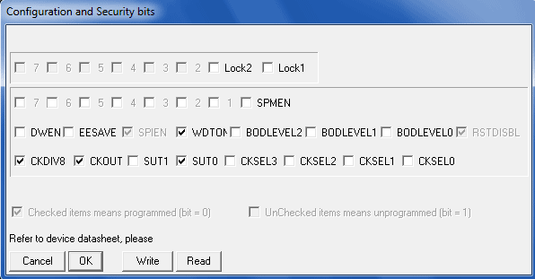
Tinyl3 is programmed using a programmer, and the setting of fuse-bits of the microcontroller is shown in Fig. 7.28.

Rice. 7.28. Setting the fuse-bits of the microcontroller


Popular
- Quantum model of personality evolution
- Sell sales to everyone
- Selling secrets for all occasions
- Deming William Edwards New Economy Edward Deming New Economy
- How to register a company abroad?
- How the passenger pays for the trip Benefits of travel for corporate orders
- Organization of a paid extended day group as an idea for a private business!
- Own business: using thermal imaging cameras to inspect houses Thermal imaging cameras as a business can you make money
- Technology and timing of installation work
- Serbia - the life of Russian emigrants in the Balkans Cost and terms of company registration in Serbia