Scale model of a tower crane kb 160. Catalog tower cranes
Tower cranes details
TO category:
Construction cranes
Tower cranes details
Tower cranes are one of the most common types of lifting machines used in civil and industrial construction. The crane consists of a support structure, a tower, a boom, a counterweight console, a slewing device, a cabin with control devices, a cargo and boom chain hoist, various mechanisms (lifting a load, turning and changing the boom radius, crane movement).
The movement of cranes is carried out mainly on rail tracks. Power supply of tower cranes is carried out from the alternating current network, control - by one machinist.
The advantages of tower cranes in comparison with cranes of other types are as follows: the location of the crane booms at a high height, as a result of which they do not cross the structure of the object being mounted; the possibility of servicing from one parking lot one or more mounted objects (spans), as well as assembly and storage sites; ease of movement of cranes along the crane runways; good review assembly area crane operator. Tower cranes are simple and reliable in operation.
-
Among the disadvantages of many models of tower cranes are the significant duration and high complexity of installation, dismantling, relocation of cranes and installation of crane runways. One-time costs for these operations reach 30-40% of the total cost of operating cranes. The new models of cranes provide for a number of design solutions (block mounting, self-lifting, etc.) that reduce operating costs and the time for preparing machines for work.
Currently, tower cranes of a single unified series of the KB series are being mastered. Models KB-16, KB-60, KB-100.0, KB-100.1, KB-100.OM, KB-160, KB-160.1/M, KB-160.2 and KB-160.4 are mass-produced.
The variety of known models of tower cranes in terms of their performance solutions and related technological capabilities of crane use in the construction industry is characterized by the following four groups of factors (Fig. 119): from the departure of an arrow; the design of the crane structure; 3) the method of movement of cranes; 4) the method of their installation and dismantling.
For the convenience of choosing a crane, all 71 models are divided according to their lifting capacity into 3 groups: 1) cranes with a lifting capacity of up to 5 t with a load moment of up to 150 tm 2) cranes with a lifting capacity of 7-10 t with a load moment of up to 110 tm \ 3) cranes with a lifting capacity of 20-75 g cargo moment up to 1425 tm.
Tower cranes with a lifting capacity of 1.5-5 tons
The group of tower cranes with a lifting capacity of 1.5 to 5 tons is the most numerous, since until recently these cranes mainly ensured the performance of installation and loading and unloading operations in housing and civil construction and in a number of industrial construction sectors. With the growth of the industrialization of construction and the increase in the weight and size of the mounting elements, the scope of these cranes has narrowed significantly. They are used in agricultural and some types of housing and civil construction.
V this group includes a significant number of cranes, in which the lifting capacity and lifting height of the hook change smoothly when the boom length changes (models BKSM -5, KB-60, BK-215, BKSM -5M, S-390, BK-3, SBK -1M, etc. ). Cranes BKSM -5-5A, M-3-5-5, BKSM -5-10, M-3-5-10, BKSM -14, BKSM - 14M have a constant hook lifting height; their arrows can also be installed at an angle with the fixing of a cargo trolley; at the same time, the boom reach remains constant.
The nature of the crane structure for the models of this group is also very diverse: there are cranes with a horizontal boom and one cargo trolley (models BKSM -5-5A, BKSM -14, BKSM -14M, etc.); cranes with a lifting shunting boom (with a mechanical change in reach; models BKSM-5, BK-215, KB-60, KB-100.0, S-390, etc.); cranes with a non-shunting boom (with an adjustment change in reach; models BKSM -1M, BKSM -4M, etc.). Cranes with a lifting capacity of 1.5-5 tons have lattice booms.
Most of the previously released models of cranes in this group have a fixed tower with an upper counterweight. More progressive are cranes with a rotary tower (models BK-215, S-390, BK-370, MSK-5-20, all cranes of the KB series, etc.). Their counterweight is located at the bottom. The cranes of this group, with the exception of the BKSM-14P crane, do not have a portal that provides the passage of a train. Variable height (due to the telescopic design of the tower) have cranes BKSM -5-10 and BKSM -14M. Most cranes have a lattice tower structure; solid tubular tower - only for cranes MBTK -80, KB-100.1.
Cranes of this group are self-propelled and move along two-rail tracks on four-support undercarriages. The BGK-3/5 crane is mounted on a caterpillar undercarriage. Row of taps on crawler has a tower-boom design. There are also truck cranes with a tower and pneumatic wheel cranes of a tower-boom design *.
Most of the previously produced cranes with a lifting capacity of 1.5-5 tons are not self-erecting and are transported with complete or partial disassembly (BKSM-5, M-3-5-10, BKSM-14, etc.). Self erecting cranes latest releases(BK-215, MSK-5-20, MBTK-80, KB-60, KB-100.0, etc.) are transported fully assembled or with partial disassembly.
The load moment of the cranes is 7.5-150 tm, the height of the hook is up to 54.5 m. The gauge of these cranes is from 2.5 to 8 m.

Rice. 1. Tower crane BKSM-I

Rice. 2. Tower crane BKSH -22.5

Rice. 3. Tower crane BK-3-1.5.

Rice. 4. Tower crane BKSM -5-3.

Rice. 5. Tower cranes BK-215, BK-215A.

Rice. 6. Tower crane BKSM-5M.

Rice. 7. Tower crane S-390.

Rice. 8. Tower cranes BK-3-318 and BK-3-187.

Rice. 9. Tower crane BK-3.

Rice. 10. Tower crane SBK-1M.

Rice. 11. Tower crane-loader BKSM-5P.
For tower cranes M-3-5-5 and KTS-3-5, the lifting height of the hook is constant and No. 21 m. With a raised boom with an outreach of 16 m, the lifting height of the crane hook.

Rice. 12. Tower crane M-3-5-5.

Rice. 13. Tower crane KB-60.

Rice. 14. Graph of changes in the lifting capacity and lifting height of the hook of the M-3-5-10 tower crane.

Rice. 15. Tower cranes S-419 and S-419M.

Rice. 16. Tower crane MBTK -80.

Rice. 17. Tower crane BKSM-5-5A.

Rice. 18. Tower crane CIWK -5.

Rice. 19. Tower crane T-223.

Rice. 20. Tower crane KB-100.1.

Rice. 21. Tower cranes KB-160.8 and KB-100.0M.

Rice. 22. Tower crane T-226E.
At the BKSM-5-5A crane, the lifting height of the hook with a raised boom r with a reach of 11 m is 39 m.
At the T-223 crane, the lifting height of the hook with a raised boom with a reach of 10 m is 60 m.

Rice. 23. Tower crane BK-370.

Rice. 24. Tower crane MSK-5-20

Rice. 25. Tower crane BKSM -5-10.

Rice. 26. Tower crane T-226.
Rice. 27. Tower crane T-227.

Rice. 28. Tower crane BK-5-248.

Rice. 29. Tower crane MSK-100.

Rice. 30. Tower spot BKSM -14.
Rice. 31. Tower crane BKSM -14M.
Tower cranes with a lifting capacity of 7-10 tons
A group of tower cranes with a lifting capacity of 7-10 tons is most widely used in housing and civil construction. A number of crane models of this group are used in the installation of unified sections of industrial workshops, multi-storey buildings of factories
radio engineering, electronic and other industries, as well as in the construction of separate special structures of large industrial complexes. Cranes of this group are also included in sets along with heavy-duty cranes (25-75 g) and are used as specialized machines for the installation of relatively light enclosing and other industrial structures, where the use of heavy cranes is not economically feasible. These cranes are also widely used in loading and unloading operations.
The nature of the change in the load capacity and the lifting height of the hook, depending on the reach of the boom, for cranes of this group is very diverse. So, for example, for cranes M-3-5-5G1, BTK -100, the lifting capacity and lifting height change smoothly; for cranes BTK -5/8, KTS -5-10R, the lifting capacity changes in steps at a constant hook lifting height; cranes MSK -7.5/20, BKSM -5-5B, KB-160, MSK -8-20, KB-160-1/M have a constant lifting capacity.
According to the nature of the crane structure, the models of this group can be divided into cranes with a horizontal boom and a cargo trolley (BTK -5/8, KTS -5-10R, BKSM -5-5B, BKSM -8-5) and cranes with a lifting shunting boom ( MBTK -75, BTK -100, etc.). The design of the boom is lattice.
Cranes BTK -5/8, MBTK -75, BTK -100, KB-160-1/M are distinguished by the presence of a rotary tower of a solid tubular structure and a lower counterweight; MSK-7.5/20, KB-160, MSK-8/20 models have a rotary lattice tower with a lower counterweight. All cranes of this group (with the exception of the M-3-5-5P model) do not have a portal that provides the passage of a train.
Cranes move self-propelled along two-rail tracks on four-bearing bogies, except for BTK-YuO and BTK-5/8 cranes, which have three-bearing bogies.
Most of the cranes in this group are non-self-erecting, transported with full or partial disassembly.
Load moment of cranes 84-110 tm; hook lifting height - up to 65 m; track width 4.5-9 m.

Rice. 32. Tower crane S-419U.

Rice. 33. Tower crane MSK -7.5 / 20.

Rice. 34. Tower crane BKSM -8-5

Rice. 35. Tower crane BTK -5/8.

Rice. 36. Tower crane KB-160.2.

Rice. 37. Tower crane MBTK -75.

Rice. 38. Tower crane BKSM-5-5B.

Rice. 39. Tower crane MSK-8-20.

Rice. 40. Tower crane KTS -5-10R.
The lifting capacity of the BKSM-8-5 crane is constant with an outreach of 4.5 to 3.7 m (8 t) and with an outreach of 13.7 to 22 m (5 t). The lifting height of the hook with a raised boom with a reach of 11 m is 39 m.
The BTK-5/8 tower crane has a constant lifting capacity at an outreach of 4.5-18 m (8 t) and an outreach of 18-30 m (5 t). The lifting height of the hook with a raised boom with a reach of 21 m is 54.5 m.
Tower crane KB-160.2 can be equipped with a jib (KB-160.4). The lifting capacity of a crane with a jib with an outreach of 13 m is 3 tons, with an outreach of 25 m - 2 tons; the hook lifting height is 66.5 and 59.5 m, respectively.
The retractable crane tower KTC -5-I0P can be installed in height in two positions. In the first position of the tower, the lifting height of the hook with the horizontal position of the boom is 13 m; when installing the boom at an angle with a reach of 17.5 m, the lifting height of the hook is 26 m, the lifting capacity is 5 tons.
In the second position of the tower, the height of the hook is 20 and 28.5 m, respectively.
The M-3-5-5P crane can be equipped with single-rope grabs for round weights and for inert materials. The design of the crane gantry ensures the pro-usk train.

Rice. 41. Tower crane loader M-3-5-5P.
Tower cranes with a lifting capacity of 20-75 tons
Cranes with a lifting capacity of 20-75 tons are in most cases used as the main assembly machines in the construction of large industrial facilities and special engineering structures (blast furnace, open-hearth, converter shops, thermal power plants, cooling towers, heavy engineering shops, etc.).
Most of the cranes of this group are distinguished by the combined nature of the change in load capacity and the height of the hook when the boom length changes. The cranes are equipped with lattice-type lifting shunting booms. Some models (BK-300, BK-1425, etc.) use interchangeable arrows of various lengths, as well as arrows with jibs up to 10 m long.
Most models of cranes in this group have a fixed lattice tower with a counterweight on top; cranes BK-1000
and BK-1425 have a turret. The height of the towers for cranes BK-25-48 (T-1 T-2, T-3), BK-1425 can be changed by using unified inserts (sections) of the tower. The cranes of this group (except for the BK-25-48 model) do not have portals for the passage of trains.
A number of previously released models of cranes in this group are non-self-propelled (BK-25-48, BK-402, etc.). Cranes BK-300, BK-1425, as well as some modernized models of cranes from previous years, are installed on self-propelled four-support undercarriages moving along two- and four-rail crane tracks. All cranes are non-self-erecting and transported with complete disassembly.
The load moment of the cranes is 160-1425 tm\ the height of the hook is up to 90 m\ the gauge is 5-10 m.

Fig. 42. Tower crane SKU-101 (scheme 1).

Rice. 43. Tower crane SKU-101 (scheme 2)

Rice. 44. Tower crane SKU-101 (scheme 3).

Rice. 45. Tower crane SKU-101 (scheme 4).
Power point crane - diesel engine KDM -46 with a capacity of 93 liters. With. with a speed of 1000 rpm-, alternator SG-60/6; the total installed power of electric motors is 62.5 kw.

Rice. 46. Tower crane MK-20-14.

Rice. 47. Tower crane KBGS -101M.
At the KBGS-101M crane, the load capacity is constant: with an outreach from 6.5 to 18 m -25 g; with a departure from 18 to 30 m - 13.5 t; at a departure from 30 to 40 w - 10 tons. The park is equipped with two cargo trolleys. Loads up to 10 tons are lifted by the front bogie, loads over 10 tons - through the traverse with both bogies.
Rice. 55. Tower crane BK-1000: 1 and 2 - the lifting capacity of the main hook when reeving the cargo shmirpzsta, respectively, in 6 c 4 chntrk.
The BK-900 crane is a reconstructed model of the BK-406A crane. The crane boom can be equipped with a 5 m long jib with a constant lifting capacity of 8 t at a reach of 15-45 m and a hook height of 43-85 m.
The boom of the BK-1000 crane is equipped with a jib with a constant load. with a capacity of 5 t with a reach of 20 to 50 m and a lifting height of the auxiliary hook up to 93 m.

table 2
Technical characteristics of tower mobile cranes for loading and warehouse and zero cycle works


Fig.8. The main parameters of tower cranes:
a - with fixed tower and lifting boom;
b - with a fixed tower and beam boom.
For tower cranes, usually the maximum possible lifting capacity, determined by the conditions of crane stability, is only the lifting capacity at the longest reach of the boom. It is the main characteristic of the crane and fits into its passport. The lifting capacity of these cranes at the shortest reach is only twice the lifting capacity at the longest reach (in some cranes the lifting capacity is constant at all departures). This rule does not apply to heavy cranes used in industrial construction, the range of lifting capacity of which at different departures is much wider.
A similar difference between tower cranes and jib cranes due to their lesser versatility, greater specialization, in connection with which a large carrying capacity at the smallest reach of the boom would not be used during operation, but at the same time it would make the crane more complex, heavier and more expensive: a more powerful engine, a larger winch and boom would be required; it would be necessary to equip the crane with a stronger rope and hook, etc.
Arrow length called the distance between the centers of the axis of the heel of the boom and the axis of the head blocks.
outreach called the distance between the vertical axis of rotation of the boom, passing through the centers of the support cart or portal, and the vertical axis passing through the center of gravity of the lifted load and coinciding with the center of the hook clip.
lifting height of load hook called the greatest possible height of its rise from the base of the crane. For ground tower cranes traveling on rails, this height is measured from the head of the rail. For such cranes, the lifting height of the hook is determined by the height of the tower and the excess of the boom head over the fifth boom hinged on the tower. This excess is provided by changing the angle of the boom. The lifting height of the load hook determines the possible lifting height of the load. A crane installed on a building and rising as it is erected is capable of lifting loads on great height than this is ensured by the height of the tower and the rise of the boom. In this case, when determining the lifting height of the load, the height of the crane base above the ground is taken into account. The load lifting limit for such cranes is determined by the rope capacity of the winch drum. Therefore, for cranes installed on buildings and structures, along with the lifting height of the load hook, the rope capacity of the winch drum for lifting the load is indicated, which is determined by the longest rope wound on the drum.
Possible boom rotation angle called the largest angle by which it is able to rotate around the vertical axis of the crane.
Depending on the possible angle of rotation of the boom, cranes are divided into full-turn and part-turn. Full slewing cranes are called those in which the angle of rotation of the boom is 360 °. Partial slewing cranes are those cranes in which the angle of rotation of the boom is less than 360 °.
The booms of full-slewing cranes, depending on the design of the slewing mechanism, can be rotated around the vertical axis repeatedly or once. Most of the existing tower cranes provide the possibility of repeated rotation of the rotary part. A single rotation takes place when a cable transmission is included in the rotary mechanism (for example, at the BTK-30 crane).
Lifting or lowering speed is the distance traveled vertically by the load per unit time. The speed of lifting and lowering the load is measured in meters per minute (m/min) or meters per second ( m/s).
rotation speed called the number of revolutions of the rotary part of the crane per unit time. Rotational speed is measured in revolutions per minute ( rpm).
Crane travel speed is the distance traveled by the crane per unit time. Movement speed is measured in meters per second ( m/s) or in kilometers per hour ( km/h).
The power of the power plant is the power of the engines installed on the crane. Along with the power of the individual motors, the total power of all motors is given. The power of internal combustion engines and steam engines is measured in horsepower (hp), the power of electric motors is measured in kilowatts (ket).
Knowing the power of the engines and the degree of their loading makes it possible to determine the power of the energy source required for the operation of the crane and the fuel consumption.
Crane performance called the number of goods processed by the crane per unit of time, which is measured in tons per hour (t/h) or tons per shift (t/shift). In construction, sometimes the performance of a crane is measured by the number of cycles performed per unit time by the crane.
The weight of the crane is determined by the weight of metal structures, mechanisms and ballast. Ballast is an additional load that provides the necessary stability of the crane. The role of ballast in the crane is performed by concrete slabs, cast iron ingots and other material. The technical specification indicates the structural weight of the crane without ballast and the total weight of the crane with ballast.
The lifting capacity of a crane is measured in tons or kilograms. Typically, the lifting capacity of the crane is assigned from the condition of ensuring its stability. For boom caterpillar, railway, automobile cranes, the highest lifting capacity corresponds to the smallest boom reach; as the reach of the boom increases, the lifting capacity of the crane decreases. The load capacity at the smallest outreach of self-propelled jib cranes exceeds the load capacity at the longest reach by several times. Load capacity fits into the passport of the crane and is its main characteristic.
Tower crane selection.


Fig.9. Tower crane selection.
Working cycle crane consists of three stages:
I seizure of cargo ;
II working stroke (cargo movement, unloading);
III idling (return of the hoisting mechanism to the
running position).
Worker and idling on motion diagrams also have three characteristic areas:
1 - acceleration,
2 - steady motion.
3 - and braking.
Moreover, the acceleration and deceleration sections are very important, since it is at these moments that dynamic loads occur.
Advantages tower cranes:
Good overview of the installation area by the crane operator;
The location of the boom at a high height, as a result of which it does not
crosses the structure of the object under construction;
Simplicity and reliability in operation;
Large linear dimensions of the working area.
TO shortcomings relate:
▬ the need for installation of crane tracks (for mobile
▬ as well as the need to install and dismantle the crane when
its relocation.
Classification. Tower cranes differ from each other in the main data of their characteristics (load capacity, boom reach, lifting height), which determine their purpose in construction.
To begin with, it should be noted that the above classification cannot fully reflect all existing species cranes, since many are located on the borders of the presented points, or they combine them.
A). By appointment allocate:
● cranes general purpose :
For civil engineering,
Industrial construction;
Hydrotechnical construction;


Fig.10. General purpose cranes:
a - lattice structure; b - telescopic design.

Fig.11. Tower crane for hydraulic engineering construction.
Load capacity b.k. for housing and public buildings up to 15 T. In industrial and hydrotechnical construction - up to 75 T.
● special taps- for industrial construction;
● high-rise cranes:
▬ self-elevating(a crane installed on a structure under construction and moving upwards using its own mechanism as the structure is erected),


Fig.12. Self-elevating tower crane.
▬ creeping(having worked in one area, the design bureau lifts itself and installs itself in a new place. In the construction industry, they received the expressive name "creeping cranes").
How does the crane “crawl” and how does it lift itself? These mechanical "miracles" are provided by the design of the crane itself. A metal lattice cage is put on the crane tower, capable of moving freely along, along the height of the tower. The clip is equipped with folding paws, which during operation serve as additional supports for the crane, increasing its stability. When the installation in one section ends and the crane needs to move higher, to the next tier, the support legs are folded, the clip is released and, pulled up by the winch, slides freely up the tower. Such a simple but ingenious design allows the crane to lift itself, as if crawling from floor to floor.


Fig.13. "Crawling" tower crane.
▬ and attachment cranes;

Fig.14. Attached tower crane.
Construction cranes for high-rise construction are used for the construction of multi-storey civil and industrial buildings of great height ( up to 150m and more).
Cranes for high-rise construction are made in attached design. The design of such a crane rests on the ground and on the frame of the building being erected. Cranes for high-rise construction also include jack-up cranes, which are sometimes called creeping and: the structure rests on the building and moves vertically - as the structure being built grows).
● loader cranes: are performed on the base and using general-purpose crane assemblies and are lowered with a horizontal boom and have a load capacity of 5 in all positions of the cargo trolley T.

Fig.15. Loader crane.
They are used to perform loading and unloading and storage operations for lifting and moving building products, structures and goods in open warehouses, construction industry landfills, as well as construction sites. Structurally, they differ from other tower cranes by an underestimated tower. The boom of loader cranes is beam, with a cargo trolley.
B). Possibility of moving distinguish:
■ mobile:
▪ self-propelled,

Fig.16. Self-propelled tower crane.
▪ and trailed;
■ stationary:
attached,
AND universal e;
Stationary cranes include cranes fixed on a foundation or on another fixed base and serving the structure under construction from one side. At high heights, to increase strength and stability, stationary cranes are additionally attached to the structure under construction. In this case, they are called attachments.
■ self-elevating.
V). According to the method of installation, movement around the construction site and type of undercarriage are divided into the following types:
Mobile on:
rail track,
on car chassis,
On a special pneumatic wheel run,
On caterpillar tracks
And walking running gear;
TO mobile include cranes equipped with a running gear and moving during operation. Mobile tower cranes also include: self-propelled, equipped with a mechanism with an independent power source for movement during operation and transportation, and trailed, which are made without a mechanism for movement and move from one installation site to another in a trailer behind a tractor (tug).
These cranes differ from each other in the design of the undercarriage.
The most widespread rail tower cranes (i.e. on a rail undercarriage), since the installation of a crane on rail tracks simplifies their operation and increases safety.
To the tower truck cranes include cranes mounted on a vehicle chassis. If the tower crane is mounted not on the chassis of a mass-produced car, but on an automobile-type pneumatic wheel chassis specially made for the crane (i.e., equipped with a cab), this crane is called a light crane on an automobile-type chassis. If the pneumatic wheel chassis under the crane is made without a cab, the crane is called a pneumatic wheel tower. Crawler tower cranes are mounted on a crawler undercarriage. They differ in complexity and large mass of the undercarriage. At the same time, the presence of pneumatic wheels and caterpillars makes it possible to do without rail tracks, which increases the mobility of the crane and speeds up its commissioning.
Tower walking cranes combine elements of rail and walking motion. Leaning on a cylindrical shoe, the crane rises above the ground together with the running frame 2, after which it moves forward. The undercarriage is then lowered to the ground and the shoe raised. With the help of running wheels 3, the crane moves along the frame forward by a step t. Then the shoe is lowered to the ground, ending the walking cycle.

Fig.17. Types of cranes by type of undercarriage:
a - rail, b - automotive, v - on the chassis of an automobile type,
G - pneumatic wheel, d - crawler, e - walking; 1 - shoe,
2 - running frame, 3 - running wheels: 4 - crane travel step
Stationary - installed on the foundation;
Attached on the foundation or on rails, attached
riveted to the structures of the building or structure under construction;
Self-elevating, mounted on structures
dimmable building or structure and moving from one
level to another using our own mechanisms
as the building is being built.
Stationary and self-elevating cranes are mainly used in the construction of multi-storey and high-rise buildings.


Fig.18. Tower cranes:
a – stationary; b - self-elevating; v - mobile.
G). According to the design features distinguish two main types tower cranes:
With a fixed tower, rigidly fixed to the chassis
howling frame or foundation;
And a rotary tower mounted on a running frame and
attached to a rotary device.
In fixed tower cranes, the slewing ring is located at the top of the tower. At the same time, the rotary part of the crane consists of a boom, a swivel head and a counter-spring console with winches placed on it, a turning mechanism and a counterweight that serves to balance the crane during operation.
In cranes with a slewing tower, the slewing device is usually located at the bottom, directly on the crane chassis or portal. In this case, the turning part includes a boom, a tower with a head and a strut, a turntable with cargo and boom winches placed on it, a turning mechanism and counterweight plates.


Fig.19. Types of tower cranes:
a - with a fixed tower (with a swivel head);
b - with turret.
D) According to the type of booms used cranes share into two groups:
with lifting,
And with a beam arrow.
For cranes with a lifting boom, the load is suspended from the end of the boom. The change in reach (boom lifting) in this case is carried out by turning the boom relative to the support hinge.
For cranes with a girder boom, the load is suspended from a cargo trolley, which moves along the boom guide beams when the reach changes.
The most simple in design and method of manufacture are lifting booms, which have become widespread.
E). By power tower cranes are divided into:
a) cranes of low power with a lifting capacity of up to 5 T for maintenance of low-rise civil construction;
b) medium power cranes with lifting capacity from 5 before 25 T for maintenance of multi-storey civil and industrial construction;
c) high power cranes with lifting capacity 25-75 T and sometimes up to 100 T for the installation of prefabricated structural elements in hydraulic engineering and industrial construction.
Tower crane indices.Each model of a tower crane (according to GOST 13555-79 "Tower cranes") has its own brand, which includes letters and numbers.
Letters mean :
KB - tower crane;
KBM - tower crane of modular system;
KBGS - tower crane for hydraulic engineering construction
KBR - tower crane for repair purposes.
The letters are followed by threenumbers in the following order:
First digit- designates the size group according to the load moment:
1st size group - 25 t m;
2nd size group - 60 t m;
3rd size group - 100 t m;
4th size group - 160 t m;
5th size group - 250 t m;
6th size group - 400 t m;
7th size group - 630 t m;
8th size group - 1000 t m;
9th size group - more than 1000 t m.

Fig.20. Scheme of indexing tower cranes.
Second and third digits- serial number of registration of cranes, distinguishes between the type of tower:
from no. 01 to no. 69 - means that the crane is equipped with a
company tower;
from no. 71 to no. 99 - means that the crane is not equipped with
for example, “.24”, which differs from the base model in technical characteristics (in the base version, the number “.0” is not indicated).
After the execution number, the letters A, B, C, ..., M, ..., Y indicate the next modification (A - the first, B - the second).
T - tropical.
TV - tropical humid.
HL - cold (areas of the Far North, down to −60 °C).
Thus, for example, cranes:
KB-308- tower crane of the third size load group (3), equipped with a swivel tower (Reg. No. 08), of moderate design.
KB-309HL- tower crane, the third size group of load capacity (3), equipped with a slewing tower (No. reg. 09), execution HL (Regions of the Far North).
KB-403B- tower crane, the sixth size group of load capacity (4), equipped with a swivel tower (No. reg. 03), second modification (B).
KB-674A- tower crane, the sixth size group of load capacity (6), equipped with a fixed tower (No. reg. 74), the first modification (A).
Some brands of tower cranes were indexed according to a different principle:
Crane KB-100- tower crane with a load moment of 100 t m.
Crane BK-300- tower crane with a load moment of 300 t m.
Crane BK-1000- tower crane with a load moment of 1000 t m.
Crane BK-1425- tower crane with a load moment of 1425 t m.
Crane ABKS-5- automobile tower crane for agriculture
construction, carrying capacity of 5 tons.
Crane KP-300- loader crane with a load moment of 300 t m.
Index "BCSM» stands for Tower Crane Self-erecting. Further, through a hyphen, the height of the rise (in floors) is indicated. After the modification, the letter M was added.
Tap BKSM-3-5-10- tower crane self-erecting for 10-storey building.
Faucets with this index were produced in the 1950s and 1960s.
General arrangement of tower cranes. The variety of applications leads to differences in the design of tower cranes. Depending on the purpose, their supporting part, tower, boom, undercarriage and other structural elements are performed differently.
However, according to their design, it is advisable to divide all tower cranes into three groups:
I - cranes with a fixed (fixed) tower and rotation
ny head;
II - cranes with a turntable;
III - cranes with a slewing tower.
All cranes of the KB series have a single design. Any tower crane consists of:
● towers (columns),
● working boom,
● supporting part,
● turntable,
● fences, stairs, platforms, driver's cab and
counterweight,
● mechanisms for the implementation of working movements:
load lifting mechanisms,
arrow turning,
departure changes,
● safety devices (load limiters -
capacity, lifting height, cargo movement
trolley, swivel and boom lift),
● control system.
All crane mechanisms are controlled by the driver from the cab, which houses the control equipment.

Fig.21. Tower crane:
a - with turret and lifting boom, b - with fixed tower
and beam boom; 1 - hook suspension, 2 - arrow, 3 - head, 4 - cabin
on the, 5 - spacer, 6 - tower, 7 - boom pulley block, 8 - counterweight, 9 - str-
fishing winch, 10 - cargo winch 11 - turning mechanism 12 - turn-
platform, 13 - slewing device 14 - ballast, 15 – chassis
frame, 16 - undercarriage, 17 - cargo trolley, 18 - trolley winch
19 - counterweight console.
Designs of cranes with swivel heads have the following main disadvantages:
1) the presence of a significant bending moment and an increase in compressive force due to the upper attachment of the head, counterweight, etc. make the tower structure and its supporting part heavier;
2) the upper fastening of the counterweight and the swivel head increases the center of gravity of the crane structure and the center of application of wind loads, which leads to a decrease in the stability of the crane and requires an additional increase in the ballast that weights the crane and its support-running part;
3) the presence of a swivel head with a counterweight console and ballast on it significantly increases the complexity of mounting and dismantling the crane and its transportation.


Fig.22. Self-elevating crane:
1 - turning part; 2 - fixed tower;
3 - screw for extending the fixed tower;
4 - support frame; 5 - lower support.

Fig. 23. Turntable of a tower crane of the 3rd size group:
1- ring beams; 2 - console part; 3 - bipedal stance;
4 - boom winch; 5 - cargo winch; 6 - turning mechanism;
7 - support bracket for mounting the tower.
Crane towers . The tower of the crane is designed to provide the required lifting height of the load, the perception and transfer to the supporting part of the loads acting on the crane.
Crane towers are a lattice steel structure of rectangular section, welded from angle steel of various sizes. Recently, tubular tower cranes have been used, the towers of which are made of steel pipes. For convenience in the manufacture and transportation of crane towers of high height are made up of separate sections. Connected with pads and bolts. Crane towers with a height of less than 25 m most often they have a section that is constant in height, and higher towers, in order to reduce the consumable metal, have a variable section that decreases towards the top.

Fig.24. Tower design schemes:
a – a rotating tower of a tubular crane;
b - a fixed lattice tower with an internal swivel head;
v - a fixed lattice tower with an external swivel head;
G - telescopic tower.
Tower (swivel or non-rotating) provides the necessary suspension height for the working equipment and also serves to accommodate some crane mechanisms. It is a telescopic (tubular structure made of a large diameter pipe), or a lattice structure made of corners or small diameter pipes.
The crane tower is a metal structure that provides the required lifting height.
Towers and arrows can be latticed from corners or pipes of large diameter .
Tower cross section and arrows can be:
square,
Rectangular,
round,
And for arrows it is triangular with an edge down or up (;↓).
Depending on the design of the crane towers are performed:
▪ rotary,
▪ and fixed.


Fig.25. Tower.
By way of turning, tower crane can be:
Top-turning (with a fixed tower and a swivel head-
And bottom-turning (with a turntable or with a turntable
Assembling method, tower cranes can be performed:
▪ unseparable,
▪ dismantled on the ground (telescopic and folding),
▪ grown from below,
▪ and stackable from above.
The metal structure of a lattice tower consists of longitudinal angles (pipes) called belts, and diagonally located corners (pipes) - braces. The braces provide the rigidity of the tower. In terms of lattice towers, as a rule, they have a square section. Less often, towers of rectangular or triangular section are made.
Depending on the method of fastening, the towers come with rigid fastening of all four belts directly to the base or to the turntable and with hinged support of the tower and fixing it with the help of struts.

Fig.26. Varieties of crane towers depending on
from fixing methods:
a - with rigid fastening of a fixed tower;
b - the same, a rotary tower;
v - with hinged turret;
G - with top-side fastening of an arrow;
d - with the top central fastening of an arrow;
e - with side mount.
The prefabricated tower consists of four sections: the first and second sections are the top of the tower; the third section includes the driver's cab and the engine room; the fourth section is the lower broadened part of the tower.

Fig.27. Cross section of the SBK-1 tower
and joint design.
Each section is a metal truss, consisting of racks, squares, braces, scarves and butt strips. Separate sections of the tower are connected using pads and bolts. The individual elements of the ‘tower’ in the first samples of cranes were connected to each other with rivets, and later with the help of electric welding.
Special support shoes with holes for bolts are welded or riveted to the lower belt of the tower or in towers with a hipped lower part to the posts. Accordingly, support beams are welded on the portal or on the undercarriage, in which holes for fixing bolts are also drilled.
To mount the tower, special lugs are welded to it and the undercarriage or portal. When installing or dismantling the crane, fingers are inserted into the hole of these eyes, which serve to connect the tower to the portal and ensure the rotation of the tower when it is raised or lowered. In order to avoid impact when the tower moves from a vertical position during its installation, a screw jack is hinged to the base of the tower.

Fig.28. Tubular Tower Crane:
the bolted connections of the flanges are placed inside the pipe.

Fig.29. Tubular turrets:
a - a tower made of thin-walled
electric pipes;
b - the same, rolled from sheet steel;
v - rolled from sheet steel with a built-in cabin;
G - stepped from pipes of large diameter, based on
thrust bearing.
Towers come with top and side mount booms. Cranes with side mounting of both lifting and beam booms (KB-100.2, KB-674) have become widespread. With the side mounting of the boom, the support hinge is moved to the side. This allows the boom to be lowered to the lower position when it is dismantled, without complicating the design of the tower.
According to the installation conditions, the towers are divided into:
Undisassembled
telescopic,
folding,
reared,
Stackable.
Undisassembled during installation, the crane tower KB-100.1 is made of a cylindrical pipe with a diameter of 920 mm with wall thickness 5 mm. The support lugs at the bottom of the tower are set apart for better load perception and have a base.
On the turntable, the turret is hinged and held in position by two telescopic treadmills. The upper tower ends with a conical cap. At a height, the tower has a bracket on which the cabin is mounted. and the abine is led by a staircase placed inside the tower. They enter the tower oez the end of the pipe open from below. An oval hole, a hatch, is provided for exiting the tower near the Chped cabin. There are gratings on the back side of the tower. Ropes and blocks of the boom block are laid on them during the dismantling and transportation of the crane.
The BKSM-5-5A crane tower also has a non-disassembled design. Its lower section is fixed on the portal. For the perception of the increased loads acting on it, this section is widened. The upper part of the tower is loaded much less, so the top section of the tower is smaller in plan.
telescopic tower has a crane KB-100.2. It consists of outer (support) and inner (retractable) sections. The support section of the tower is pivotally connected to the turntable from below. At a height of 3.4 m, two brackets are welded to the tower to secure it with telescopic struts during operation and transportation.
The retractable section of the tower in the extended position rests with its supporting platforms on the side stops of the outer section and is centered in it with two rows of pins. A platform for a cab, a ladder inside the tower, a strut and a head are attached to the retractable section. To extend the inner section, a four-fold mounting chain hoist and a rod, with its upper end resting against the support shoe of the retractable section, are used.
faucet heads. The tip serves as a continuation of the tower and is intended to keep the boom in working position with the help of arrow ropes or rods. On some cranes (for example, ABKS-5), the head is replaced with hinged ones, which makes it possible to reduce the length of the crane during transportation.
The head of the tower crane is a truss of tubular elements. The truss ends with a box, in the nests of which there is an axle with two outlet cargo blocks. The axle is fastened with clamps and clamping bars. During installation and maintenance, ladders were installed to climb the headroom and access the blocks. There are two lugs for fixing the braces of the main boom and the counterweight console.

Fig.30. Head of the crane KB.
in the faucets, with a swivel turret, the heads are rigidly connected to the turret. At the top of the head, deflecting blocks of cargo ropes and boom ropes are attached.
The configuration of the head is selected by the designer during the design. When the tip is moved forward (toward the boom), the conditions for horizontal movement of the load are improved when the reach changes for cranes with lifting booms. When the tip is moved back, the stability of the arrows from tipping over increases when working at short reach.
In taps with a fixed tower, two types of heads are distinguished: fixed and rotary.
In cranes with bell-type slewing devices, the non-slewing head is rigidly attached to the top of the non-slewing towers. In many designs of cranes, there is no fixed head. In this case, the swivel head, which also serves as a support for the entire swivel part of the crane, is connected to the top of the tower by a glass-type slewing device or in the form of a ball (roller) circle. In this case, the tip configuration (as in slewing tower cranes) depends on the tasks that the designer sets himself when creating the crane.
Crane heads. All tower cranes, with the exception of those that have swivel columns, can be divided into two groups, differing in the design of the swivel parts - heads.
The first group includes valves with enclosing swivel heads. The head in these cranes, located at the top of the tower, consists of a fixed part connected to the upper section of the tower, and a swivel part, which is located above the fixed section and covers it from the outside.
The second group includes cranes with heads placed inside the tower. The head is made in the form of a lattice structure, conical or cigar-shaped, resting with its lower part on a support inside the tower.

Fig.31. Tower crane head T-72:
1 - counterweight; 2 - turntable; 3 -rack; 4 - control cabin;
5 - skating circle; 6 - transition platform; 7 - support rollers; 8 - shank;
9 - traverse; 10 - Thorn; 11 - support beam;
A - the upper support unit of the head; B - the lower support node of the head.
Working arrow. The boom of a tower crane is designed to provide the necessary area of its working area, to perceive and transfer the loads acting on it to the tower.
The booms of tower cranes are a lattice steel structure of rectangular or triangular section, welded from angle steel, and sometimes from pipes (tubular cranes). The design of the booms depends on the accepted method of applying the payload (cargo) and the method of suspension.
Working equipment consists of:
a) boom equipped with a boom-lifting chain hoist or support
arrow-spinning thrust,
b) lifting device in the form of a hook or a special grip.
The boom is used to lift loads. The load is lifted with the help of a cargo winch, a cargo rope and a hook suspension, which is the load-gripping body of the crane.
The working boom on tower cranes is:
▪ working booms with rope suspension;
▪ beam boom with cargo trolley;
▪ lifting boom made of pipes;
▪ and from the corners.
Crane boom designs. According to the method of moving the load, arrows are distinguished:
■ lifting,
■ fixed reach rigid and trolley booms.
lifting the boom is suspended from the swivel head on the chain hoist, from which the rope runs onto the drum of the boom winch. The movement of the load suspended at the end of the lifting boom is carried out by changing the angle of its inclination. In this case, the load simultaneously with horizontal movement rises or falls, describing a curvilinear trajectory.
The lifting boom is a spatial metal structure attached to the tower by means of a support hinge. At the end of the boom are blocks that can be exploded using a balancer that connects to the head of the boom. At the same time, the load is constantly suspended from blocks equipped with cargo ropes. An arrow of this type is set obliquely to the horizon, and its reach is changed by changing the angle of inclination.
The advantage of this type of arrows is the simplicity of construction.
Rigid the boom has a constant reach during the working cycle of the crane. Such an arrow is suspended from a swivel head on a flexible brace attached to the end of the boom.
To change the reach of the boom in all cases, the operation of the crane must be stopped. The movement of cargo by a crane equipped with a rigid boom is carried out when the crane itself moves along the tracks and when the boom rotates. The design of the boom works on bending from its own weight and on compression from the weight of the boom and load and is the simplest and lightest.
On the heads of the lifting and rigid arrows, the upper blocks of the cargo chain hoist and the axles for fastening the rods of the boom bracing are fixed.
Boom with a cargo trolley. The supply of cargo by a crane equipped with a boom with a cargo trolley is carried out using this trolley moving along the boom, suspended, as a rule, in a horizontal position. If it is necessary to increase the lifting height of the load, the boom is set to an inclined position, a cargo trolley with a hook is fixed at the end. In this case, the boom works as a rigid one with a constant reach.
The movement of the cargo trolley along the boom is carried out along special guides, which for light cranes can be the corners of the boom belts, and for heavy cranes - with I-beams attached to the lower plane of the boom. For most cranes, booms with cargo trolleys are suspended on rigid rods or flexible braces of constant length, attached at one or more points. The number of suspension points depends on the length of the boom and the lifting capacity of the crane.
The metal structures of the booms currently produced by cranes are welded . In old models of SBK-1 cranes, the booms were riveted .
Arrows for convenience of transportation consist of separate sections. Most arrows are made of three sections - head, middle and support.
The joints of the boom sections are connected by overlays on clean bolts or flanges. In addition to the main sections, booms are sometimes equipped with interchangeable inserts that allow you to change the length of the boom and, accordingly, the lifting capacity of the crane. Diaphragms (transverse vertical connections) are provided at the ends and in the middle of the sections to create the necessary rigidity.
Changing the reach (i.e. changing the position of the hook suspension relative to the axis of rotation of the crane) is carried out either by changing the angle of inclination of the boom using the boom chain hoist and boom winch, or by moving the cargo trolley using the trolley winch.


Fig.32. Structural diagrams of tower crane booms:
a - rigid boom with a constant reach; b - lifting boom;
v - crane boom BK-1 on rope loops; G - crane boom BKSM-3
with rope tackle; d - boom with load trolley and rigid
thrust; e - the same, lifting with flexible rods; well - the same, lifting
without traction; h - lifting boom of the BTK-100 crane boom; 1 - arrow;
2 - boom chain hoist; 3 - swivel head; 4 - tower; 5 – cargo
howling rope; 6 - cargo trolley.
Base part. The supporting part of the tower crane is designed to transfer forces from the tower through the rollers to the crane runway. The design of the supporting part is mainly determined by the weight of the crane and the gauge.
The supporting parts perceive the loads acting on the crane and transfer them directly to the crane base (crane tracks, foundation or building floors).
support part mobile tower cranes includes:
A frame that serves as the basis for installing a tower or a rotary device,
And the undercarriage, which transfers the load from the crane to the rail tracks and serves to move the crane.
Supporting parts of attachment cranes are foundation slabs. attached with anchor bolts to the foundation, and fastening frames, which are located between the sections of the tower. The frames are attached to the building with additional connections, the foundation plates are 4-to the flanges of the lower section of the tower.
Supporting part of self-elevating crane- support beams - serves to fix the crane on the floors of the structure under construction during operation. For the period of extending the crane with the help of a mounting chain hoist, a lifting cage is used as a supporting part, the guides of which slide along the belts of the tower while the crane is raised to a new mark.
The lower part of the crane, which perceives all loads and transfers them through the running wheels to the rail track, is called supporting part.
Depending on the size of the crane, its supporting part has a different design:
In cranes with a lifting capacity of 0.5-1 T the supporting part has the form of a flat cart (a);
In cranes with a lifting capacity of 1.5-5 T the supporting part is made in the form of a portal (b, c, d, e, f, g).
Portals for different models of cranes in this group have a different design.

Fig.33. Tower crane portals.
The supporting parts, made in the form of a trolley, are easier to manufacture; the supporting parts, made in the form of a portal, are more difficult to manufacture, provide the possibility of storing building materials and structures between the rail tracks, as well as the passage of vehicles.

Fig.34. Running frames:
a - asymmetric;
b - U-shaped portal;
v - tented portal;
G - with rotary beams-weathervanes;
1 - frame; 2, 4 - beams, 3 - struts, 5 - rack, 6 - sleeve, 7 - vane.
According to the number of points of support on the rails, the frames are three- and four-support. The most common are four-support frames, so consider their designs. The design of the frame depends on the type of crane (with a slewing or fixed tower) and the type of undercarriage (rail, automobile, pneumatic).
In some cranes with a fixed tower, the undercarriages are attached to the tower by means of a portal. Undercarriages on steel running wheels move along the rail crane track using the crane travel mechanism. The supporting part of stationary tower cranes is a frame mounted on a monolithic base. At high heights, tower cranes are additionally attached to the structure under construction. Such cranes are called attached. In some cases, the attached crane can work as a mobile crane up to a certain height. Then it is universal and has a supporting part in the form of a running gear similar to mobile cranes.
The undercarriage perceives and transfers to the base (soil, rail track or structure of the structure) all loads from the weight of the crane, wind and the load being lifted. On the undercarriage, as a rule, there is a mechanism for moving the crane.
Running frames of fixed tower cranes are usually equipped with rail running gear. Consider the execution of these running frames.
The flat undercarriage frame with struts comes with a central frame (usually not used for cranes with a turret) or an asymmetric frame with an offset turret.

Fig.35. Chassis.
Walking device.


Fig.36. Two-wheel drive carts:
a – with globoid reducer; b - with two helical-bevel gears;
1 - engine; 2 – brake; 3 - reducer; 4 – anti-theft grip, permanently
placed under the head of the rail.
Running trolleys of mobile rail cranes are divided into:
Driven;
And non-driven.
The carts are made on steel running wheels with flanges, which move along the crane rail track with the help of travel mechanisms.
Undercarriage of the top-slewing crane:
Left undercarriage;
running frame;
Right cart.
The crane moves around the construction site, usually with the help of a rail running gear on steel running wheels driven by a mechanism for moving along the crane tracks.
Traveling trolleys of mobile cranes - on steel running wheels with flanges, move along the crane rail track with the help of travel mechanisms.
Tower cranes mounted on automobile, pneumatic-wheeled and caterpillar chassis are made on the basis of self-propelled boom-type cranes.
Tower cranes have a multi-engine electric drive powered by an external network through a cable and current collector and perform the following working movements: lifting a load, changing the reach, turning, and mobile cranes, in addition, moving. The combination of these movements makes it possible to transport cargo to any point of the working area of the crane, as well as serve the territory of the warehouse, unload cargo from vehicles.

a B C
Fig.37. Undercarriage of the top-slewing crane:
a- left undercarriage; b - running frame; v - right cart.
Support and swivel device. Slewing devices are designed to transfer pressure from the rotary part of the crane to the fixed part and perform the working movement of the boom rotation.

Fig.38. Slewing tower crane with a rotary tubular tower:
a - scheme; b - kinematic diagram of the mechanism.


Fig.39. SOP head of tower crane:
a - design; b - central trunnion with traverse.
To connect the rotary and non-rotary parts of the crane is used slewing device (abbr. SLE - slewing device), which provides both the transfer of vertical and horizontal loads from the slewing part of the crane to the non-slewing running frame, as well as overturning and torque from the slewing part of the crane to the non-slewing part, and rotation of the slewing part relative to the non-slewing frame.

Fig.40. Rotary part of the crane KB.
Distinguish four types slewing devices:
With spaced bell-type and glass-type supports,
With ball and roller wheels.
GTC bottom slewing crane with a slewing platform is located below, directly on the supporting part of the crane or on the portal.
The swivel part of the crane rotates relative to the fixed part with the help of a swivel mechanism. Both parts are connected by a slewing mechanism that transfers vertical and overturning loads from the swivel part to the non-swivel - running frame.
The rotary part includes: a rotary platform with working mechanisms of the crane placed on it - cargo and boom winches, mechanism

Fig.41. Single row ball bearing:
a - scheme; b - node location of the balls.
turn. In addition, counterweight plates, a tower with a head, a strut and an arrow are installed on the platform.
On top-slewing cranes, the platform with the tower installed on it does not rotate. The launcher of such a crane is located in the upper part of the tower structure. For the possibility of moving loads along an arc, a swivel head is installed on the tower, to which a counterweight console with a counterweight is attached to balance the boom. The working mechanisms are installed on the counterweight console.
Modern tower cranes with a fixed tower have a lifting capacity of more than 10 T. Increased lifting capacity and lifting height result in a large overall weight, which makes it difficult to build cranes with a slewing ring at the bottom of the machine.
The main advantage of mobile cranes with a fixed tower is the possibility of their conversion into attached cranes, which are universal and can act as self-elevating and mobile - at a low height they are mobile, and when it increases, they act as stationary attachments.
To ensure the stability of mobile tower cranes, ballast is laid on a turntable or at the bottom of a fixed tower.
A bell-type slewing device with two supports spaced apart in height is used in a number of cranes with a fixed tower (for example, BKSM-5-5A). The upper support perceives vertical and horizontal loads: the lower roller support - only horizontal. The overturning moment with this design is perceived by the horizontal reactions T of the upper and lower supports. Sometimes the vertical load is taken not by the upper, but by the lower support built into the tower. At the top of the head of the crane there is a mushroom, which has a broadened part below, with which it rests on the heel 9. The heel is fixed on a fixed head.
Horizontal loads are perceived by the support glass, fixed on the swivel head. To reduce friction when turning, bimetallic bushings are pressed into the cup, and at the point of contact of the fungus with the support cup, a bronze washer of the lower part of the swivel head is placed four pairs of road wheels. When the crane rotates, they roll along an annular bandage fixed on a fixed head.
To evenly distribute the load between adjacent rollers, they are connected in pairs to form balancing carts.
The cup-type slewing device is like an inverted bell-type device with spaced supports built into the tower. In this case, the lower support-thrust perceives horizontal and vertical loads, and the upper support - only horizontal.
Turntables with ball or roller wheels perceive loads in all directions.

Fig.42. Slewing bearings with two
height-spaced supports:
a - bell type; b - glass type; 1 - top support; 2 - swivel head;
3 - lower support; 4 - fixed head; 5 - Cup; 6 - bushings; 7 - mushroom;
8 - washer; 9 - heel; 10 - tower.
According to the number of rows of balls or rollers, circles are single-row and double-row. Double-row ball wheels are more reliable than single-row ones. These circles are three rings, between which balls are placed. The roller wheel is different in that the rollers are placed in a common chute crosswise. In this case, the roller rolls along one pair of raceways, the one following it - along the second pair of raceways. One of the rings of the circle is fixedly bolted to the supporting running frame. Bolted split rings are attached to the turntable. The connector of the rings ensures the disassembly of the slewing rings.
To reduce friction between the balls, separator short steel or plastic bushings 6 are placed. On the fixed ring 3 there is a gear ring with internal gearing that serves to turn the crane.
In this engagement, the teeth are replaced by steel turnout pins, which are fixed between two rings. This engagement is easier to manufacture, but creates increased loads on the gears and crane structures.

Fig. 43. Support - rotary device.

Fig.44. Slewing circle:
a- circle in axonometry; b- section along a ball circle with gearing; v- section along the roller circle; G - cross-section along a ball circle with lantern gearing; O- section along a two-row roller circle; 1,2 - detachable rings; 3 - fixed inner ring; 4 - ring gear; 5 – ball; 6 - separator sleeve; 7,8 - rollers; 9 - tarsus; 10 - press grease fitting; 11 - outer ring.
The roller circle with two horizontal rows of rollers, used on cranes KBk-250 and KB-503, is shown in fig. Slewing rings, balls and rollers, ring raceways, crown teeth are made of steel. Grease fittings are provided in the outer race for lubrication, which should not protrude beyond the outer cylindrical surfaces of the semi-cage.
Guardrails, stairs, platforms, cabins and counterweights. Tower cranes in accordance with the Rules of Gosgortekhnadzor have entrances from the ground to the portal (running frame) and to the cabin, as well as convenient access to stairs located above the portal (running frame).


Fig.45. Guardrails, stairs, platforms.
For the convenience of lifting the driver into the cab and on the head of the crane along the tower, they install stairs. Width of stairs leading to the cabin, not less than 500 mm. The ladder is made of two steel strips. The bands are located one from the other at a distance of 600 mm and interconnected by steps made of bar steel. Connection of steps with strips is welded. A railing in the form of clamps bent from a steel strip is attached to the stairs.
Distance between steps - no more than 300 mm, every 6-8 m platforms are arranged on the stairs. From Height 3 m, vertical stairs enclose arcs in the form of circles with a radius of 350-400 mm, which are installed at a distance of not more than 800 mm from each other and interconnected by at least three longitudinal strips. fencing in the form of arches is not required if the staircase passes inside the tower with a section of no more than 900 X 900 mm(for lattice towers) and with a diameter of not more than 1000 mm (for tubular towers). With inclined stairs (at an angle of 75 ° to the horizontal or less), the stairs are equipped with railings and have flat steps.
transitional platforms fenced with railings height 1 m. The flooring can be wood or metal. In the latter case, it is made of corrugated, corrugated or perforated materials. The sites must have a continuous fence from below to a height of at least 100 mm.
All mechanisms are controlled by the driver from the cab. On most cranes, it is located at the top of the tower, which provides a good overview of the front of the work.
Although modern cranes have remote control panels, they are used only during installation and testing of the crane. As a rule, not all crane movements can be controlled from the remote control and it is impossible to smoothly adjust the speed of the mechanisms.
Some cranes use convenient remote cabins, with a good overview of the work site, their position in height can be changed.
Since tower cranes operate outdoors at any time of the year, the cabins are closed. Tower crane cabins come in two varieties:
built-in,
And portable.
Built-in cabs. Built-in cabins are located inside the tower (or other crane structure) and are connected to its steel structure as an integral connection.


Fig.46. Built-in cabins:
a - CBK-1; b - MSK-5-20; v - MSK-5-.20A;
1 - a gap in the roof. 2 - platforms, 3 - stairs, 4 - manhole covers.
The disadvantage of these cabins:
They are inconvenient to repair;
It is impossible to insulate because of the gap in the floor and ceiling, through which it is passed
a cargo rope running from a winch located under the cab;
Hatches in the floor and roof make it difficult to access the cab and worsen the hermetic
roof quality; the cabin is small, it is crowded;
When turning the boom, the cab remains stationary and the driver, in order to
keep an eye on the load, forced to move from one window to another.
Remote cabins. Remote cabins are located outside the metal structures of the crane (tower, head). A cabin is also considered remote if it is located inside a tower with cross-sectional dimensions of more than 1.8 x 1.8 m, and the cabin itself is made as an independent unit, that is, it can be removed or inserted into the tower as a whole without disassembly.


Fig.47. Removable cabin.
Remote cabins divided into:
hanging,
And mounted.
Cabins that are suspended from the crane metal structures by the upper part are referred to as suspended.
Hinged cabins are based on the platform of the crane metal structure. In addition, these cabins can be provided with additional fastenings on the side wall or roof.

Fig.48. Remote cabins on cranes:
a - suspended on MZ-5-10, b - hinged on the BKSM-14M portal, v- mounted on KB-573 and KB-674, G - unified in the KBK-250 tower; 1 - eyelets, 2 - rods (the dotted line shows the position of the cabin during installation and transportation).
Mounted cabins located at the bottom of the crane are inconvenient to use:
They do not provide an overview of the work site during the installation of buildings: the driver, starting from the 2nd-3rd floor, is forced to work with a signalman; the load hooked from the opposite side of the tower is not visible to the driver due to the metal structures of the crane;
The driver often has to look through skylights. To prevent the windows from breaking, they are protected with a mesh, and this makes it difficult to clean the upper glasses from snow and dirt.
Suspended cabins are attached to the swivel head of the tower and therefore rotate simultaneously with the crane boom. Thus, the driver has the opportunity, without turning, to constantly see the load hook and the crane boom.
The walls of these cabins are made of boards attached to a metal frame. The roof is made of metal sheet. The upper part of the front wall is a glazed lantern extended forward. The cabin door is sliding. The disadvantage of these cabins is bulky electrical equipment, which takes up a lot of space. The driver, as a rule, works standing up due to uncomfortable glazing. In addition, the cabin is noisy due to the operation of the contactors.
Unified mounted cabins. Unified hinged cabins belong to remote. They provide maximum comfort.

Fig.49. Devices for shifting cabs along the tower of cranes:
a - MBTK-80; b - KB-YUO.OM; 1 - outlet blocks on the tower; 2 - slings;
3 - brace block 4 - cabin suspension rope; 5 - hook suspension of the crane;
6 – block; 7 - blocks attached to the cab.
On tower cranes, the most dangerous parts of the mechanisms for the operating personnel are guarded. Walkways used by service personnel to inspect mechanisms mounted on the counterweight console and for inspection of boom head units must also be guarded.
To ensure the safety of lifting the driver to the crane, ladders with railings are attached to the tower. For the rest of the workers climbing the crane and for the transition from one ladder to another, special transition platforms are arranged, which also have fences.
Most tower cranes have counterweights. The purpose of the counterweights is to unload the crane tower from large bending moments arising under the action of the load.


Fig.50. Place of counterweight KB.
The counterweight frame is pivotally attached to the lower part of the crane swivel head and suspended from its upper part on rigid rods. The counterweight rotates with the swivel head, always being on the opposite side of the boom.
Ballast attachment devices are different on different running frames. In one case, the ballast plates are laid directly on the frame (KB-572, KB-674 cranes), in the other they are hung from the side (KBR-1 cranes) - for this, lugs and fingers are made on the side walls of the running frame, on which ballast hooks are hung. From the bottom on the running frame there are support platforms for supporting the ballast plates.
The ballast on tower cranes ensures their stability both during operation and when not in operation, because the own weight of the structure is insufficient to maintain the stability of the cranes.
As a ballast, it is advisable to use inventory concrete blocks, because. the use of random materials leads to a decrease in the weight of the ballast due to its losses during transportation and crane operation.

Fig.51. Scheme of designs of counterweights:
a – motionless with fastening to a rotary head;
b - movable with a lower location at the base
rotary tower;
v – swinging with fastening to a rotary head.
Mechanisms for lifting cargo, turning the boom, changing the departure.

Fig.52. Kinematic diagrams of crane mechanisms of the crane KB-504A:
a - cargo winch; b - trolley winch; v - mounting winch; G - lift winches; d - turning mechanism; e - movement mechanism; 1 - two-stage gearbox; 2 - drum; 3 - fan; 4 - air duct; 5 - brake; 6 - DC motor; 7 - telecommunication; 8 - generator; 9 - DC machine; 10 - AC motor; 11 - angle sensor; 12 - terminal switch; 13 - departure indicator sensor; 14 - worm gear; 15 - special brake; 16 - three-stage cylindrical reducer; 17 - output gear; 18 - ring gear; 19, 23, 24 - gears; 20 - globoid reducer; 21 - driven wheel; 22 - driving wheels.
Hook hangers for tower cranes. Hook suspension brackets are load-gripping bodies of the crane. They are for hanging the load from the cargo rope. Suspensions are one-, two- and three-axle in terms of the number of axles, on which there are rope blocks. Hook hangers consist of sheet metal, between which one or more blocks 2 rotate on axles. A load hook is fixed in the lower part of the cheeks by a traverse. One- and two-axle suspensions are used on cranes with a double-line reeving of a cargo rope. For greater carrying capacity with a four-string reeving, three-axle suspensions are installed. The latter allow you to change the ratio of rope reeving depending on the mass of the lifted load.

Fig.53. Hook hangers:
a – uniaxial; b – biaxial; v - triaxial; 1 - cheeks;
2 – blocks; 3 - hook; 4 - clip; 5 – earring.
When working with light loads, the earring is disconnected from the cheeks and the clip is turned off from work. It rises up and is held on the boom head by a cargo rope due to the mass of the hook suspension, which works in this case in the same way as a two-axle suspension. For heavy loads, the suspension is lowered to the ground and the clip is lowered down. After connecting the clip with the cheeks of the suspension, four threads of the rope are involved in the work.

Fig.54. KB crane hook suspension:
1 - block; 2 - axis; 3 - cheek; 4 - traverse; 5 - hook; 6 – lock; 7 – lid;
8 - thrust bearing; 9, 10 - seals; 11 - clamping bolt.
The mass of hook hangers is selected so as to ensure their lowering without a load on the hook. The suspension must, with its weight, pull the cargo rope unwound from the winch drum. For this purpose, additional weights are sometimes hung on the cheeks of pendants.
Tower crane trucks. Cargo trolley is used on cranes with girder booms, it serves to move the suspended load along the boom. If for cranes with a lifting boom, the reach changes by changing the angle of inclination of the boom, then for cranes with a beam boom - by rearranging the cargo trolley. The cargo trolley moves with the help of ropes driven by the drum of the trolley winch.

Fig.55. Schemes of the movement mechanism of the cargo trolley and the tension device of the traction rope of the cargo trolley:
a - crane UBK-5-50; b - crane M-3-5-5: 1 - winch drum; 2 - traction
rope; 3 - blocks on the head of the tower; 4 - blocks on the arrow head; 5 - cargo
sculpting cart; 6 - tension device.
The cargo trolley consists of a welded frame 1, in the lower part of which blocks 2 of the cargo rope are fixed, and in the upper part - track rollers.
Carts are simple and balancing. Simple bogies have four rollers, balancing ones have eight or more rollers connected in pairs by balancers, which allows the specific pressure on the boom driving belt to increase the carrying capacity of the bogie. Track rollers 3 are used with or without flanges. The flanges prevent the cart from tilting when moving along the boom. On carts with flangeless rollers, guide rollers serve the same purpose.

Fig.56. Cargo trolleys:
a - simple; b - balancing; 1 - frame; 2 – block; 3 - track rollers;
4 - balancer; 5 - guide rollers.
Cargo trolleys are designed for lifting and horizontal movement of cargo along the boom. The trolley consists of:
Frame made of channels and corners,
Inside which are mounted guide blocks of the cargo rope and support rollers, with the help of which the trolley moves along the I-beam of the boom.
Carts of light cranes have four support rollers; trolleys of heavy cranes - eight each. Blocks and support rollers are mounted on ball bearings.
The trolleys have hook lifting height limiters, consisting of a system of levers acting through a special rope on the limit switch of the load lifting mechanism. Carts are equipped with special rulers, which, when in contact with switches mounted on the boom, break the circuit that feeds the electric motor of the trolley movement winch and thereby fix the extreme positions of the trolley.
Security Devices(load limiters, load height limiters, cargo trolley movement, boom rotation and lifting).
These devices include:
a) Limit switches designed to automatically stop the mechanisms of cranes with an electric drive. Limit switches are not used on mechanically driven cranes. Requirements for equipping hoisting machines with limit switches are set out in the Cranes Rules;
b) blocking contacts used for electrical blocking of the entrance door to the crane cabin from the landing site, the hatch cover of the entrance to the bridge deck and other places;
v) load limiters , designed to prevent accidents of cranes associated with lifting a load with a mass exceeding their (including hook departure) carrying capacity. Installation of the device is mandatory on jib, tower and portal cranes . Bridge type cranes must be equipped with a load limiter in the case when their overload is not excluded according to the production technology. The requirements for installing the appliance are contained in the Rules for cranes;
The crane capacity limiter is designed to automatically turn off the engine of the cargo winch when lifting a load, the weight of which exceeds the nominal capacity of the crane at a given boom reach by more than 10%. As a result of overloading, the crane may lose stability and fall, deformation and breakage of individual elements and components of the crane may occur (breakage of the cargo rope, bending of the boom and tower, cracks in the metal structure of the head and tower, breakage of the hook, parts of the cargo winch, etc.). ). The load limiter ensures the safety of work on the crane, preventing its possible overload.
The load capacity limiter consists of a lever to which a load rope thimble is pivotally attached. The lever is connected with an earring to a two-arm lever, which is connected by a wire cord to a rod fixed on the switch lever. Thus, the switch serves both limiters - the height of the hook and the lifting capacity.

Fig.57. Crane load limiter SBK-1
systems of N. I. Chernyshev.

Fig.58. Crane load limiter BK-2:
1 - plate; 2 - spring; 3 - bracket; 4 - bracket; 5 - thrust sleeve;
6 - thrust; 7 - switching ruler; 8 - cracker; 9 - boom rope;
10 - clamp; 11 - limit switch.

Fig.59. Crane load limiter M-3-5-5:
1 - thimble; 2 - lever arm ; 3 - spring; 4 - wedge; 5 - screw; 6 - screw; 7 - final
switch; 8 - drum of the winch for the movement of the cargo trolley.

Fig.60. Crane load limiter T-72:
1- rope; 2 - sector of inclusion; 3 - latch; 4÷5- springs; 6 - hinge.
G) hook height limiter designed to automatically turn off the engine of the cargo winch when lifting the hook (hook cage) to the boom at a distance less than that set for cranes during normal operation - 0.5 m. If the clip abuts against the boom and the cargo winch continues to work, the cargo rope may break, the boom and the rigid brace may be deformed, the boom may tip over onto the tower head, and even the entire crane may fall. The hook lift height limiter prevents the clip from lifting until it hits the boom head.
The load lifting height limiter consists of a two-arm lever connected by an earring to a rocker arm. The rocker is connected by means of a wire rope to a rod, the end of which is fixed on the switch lever. The lever is pulled back with a spring.
Both limiters are often made as one combined device mounted on the crane boom. The device is a lever system that acts on the limit switch, which, at the moment the load is lifted above the nominal value or the hook reaches the maximum lifting height, opens the circuit that feeds the electric motor of the cargo winch.
The limiter must have a flexible element in its circuit, which would be designed for the load permissible for the crane and, if it was exceeded, allowed the levers to change position. Such an element is most often a spiral, calibrated spring or a load suspended on a cable.
Depending on the way the load is suspended - to the cargo trolley or at the end of the boom - the limiters have a different design.

Fig.61. Crane hook lifting height limiter M-3-5-5:
1 - spring; 2 - lever arm; 3 - terminal switch; 4 - cord;
5 - guide rollers; 6 - deflecting roller; 7 – cargo
cart; 8 - limiter lever; 9 - traction rope.

Fig.62. Buoy crane hook lifting height limiter:
1 - bracket; 2 - intermediate pusher;
3 - terminal switch; 4 - lever arm.
e) skew limiters designed to prevent dangerous distortion of metal structures of gantry cranes and overhead loaders due to advance of one of the supports of the other when the crane is moving. The need to install the device is determined during the design calculation;
e) load indicator , installed on boom-type cranes, in which the lifting capacity changes with a change in the hook reach. The device automatically shows what the crane's capacity is at the set reach, which helps to prevent overloading of the crane;
g) tilt angle indicator for correct positioning of jib cranes , except for those working on railroad tracks;
h) anemometer . Such a device should be equipped with tower, portal and cable cranes for automatic sound signaling at wind speeds dangerous for work;
and) anti-theft devices used on cranes operating on ground rail tracks to prevent wind from stealing them. The requirements for these devices are set out in the Crane Regulations;
To protect the crane from accidental movement and overturning under the influence of strong winds, etc., anti-theft grippers are installed on the crane undercarriage or on the portal.

Fig.63. Tower crane anti-theft grapple


Fig.64. Anti-theft grips:
a - brought under the rail head; b - clamping the rail head;
v - the same with two hinges.
To) automatic dangerous voltage signaling device (ASON), signaling the dangerous approach of the crane boom to the live wires of the power line. The device is equipped with jib self-propelled cranes (with the exception of railway ones);
l) supporting parts , which are supplied with bridge-type cranes, mobile cantilever, tower, portal, cable, as well as cargo trolleys (except for electric hoists) to reduce dynamic loads on the metal structure in case of breakage of the axles of the running wheels;
m) stops installed at the ends of the rail track to prevent the descent of lifting machines from them, as well as on jib cranes with a variable reach of the boom to prevent it from tipping over;

Fig.65. Crane end stop design:
1 - emphasis; 2 -buffer; 3 - bolt.
m) an audible signaling device used on cranes controlled from the cab or from the remote control (with remote control). On cranes operated from the floor, a signaling device is not installed;
O) boom limit stop . On cranes with lifting booms, the change of the reach of which is carried out with a load using electric winches, limiters of the extreme positions of the boom are installed.
Lack of boom limit stops may cause the boom to fall onto the pivot head or down. In both cases, failure of individual elements of the crane and even its accident can occur.

Fig.66. The results of breakdowns of elements of cranes:
a - arrows; b - towers.

Fig.67. Crane with a broken three-arm boom.

Fig.68. Breakage of the crane head due to frequent impacts
in gears of the turning mechanism.

Fig.69. A tower crane that fell in St. Petersburg
on a 12-storey building (two dead).

Fig.70. Tower crane fell (Barnaul).
Control system serves to control the operation of crane mechanisms. The control system of electrically driven cranes consists of controllers or magnetic starters and brakes with electromagnets.
The tower cranes catalog includes modern brands of the KB series Russian production and German, Spanish, Chinese models of the following brands: Liebherr, Potain, Terex Comedil, Comansa, Zoomlion, Jaso, Saez / Saez, XCMG with specifications. The tower crane is designed for mechanization of lifting operations for the delivery of various building materials to a height during the construction of high-rise multi-storey office buildings, residential buildings, skyscrapers.
The structure of the tower crane includes individual sections of the tower, a lifting or beam boom, a cabin, a cargo / undercarriage and a rolling cart for transporting a crane, a slewing device (SLE) and a turning mechanism, a cargo winch, a boom lifting mechanism, a carriage, dead ends, rail ( crane) tracks, set of counterweights, base: rail (crane) tracks, support frame, foundation with anchor fastening.
All modern brands of tower cranes are self-erecting (self-elevating) and do not require separate lifting mechanisms. Mounting / dismantling of individual sections is carried out with a special regular hydraulic jack. The boom is also assembled from sections on the ground and mounted on a crane with a special lifting mechanism. Depending on the version, the base of the tower crane is installed on a rail (crane) track, a frame or anchored to a concrete foundation, and individual sections of the tower are already mounted on the base, one after the other, until the maximum height is reached.
According to the classification, tower cranes can be mobile on rails (rails), stationary (on a foundation), attachments for high-rise construction (on a frame), with a slewing / non-slewing tower, with a lifting or girder boom. In the attached version, a special anchor fastening of the tower crane to the building under construction is used.
tower crane photo
Tower construction cranes are designed to perform construction and installation and loading and unloading operations. The tower crane consists of a tower (column), an arrow, a supporting part, a slewing device, a driver's cab, mechanisms for lifting cargo, turning the boom, changing the reach, safety devices (load limiters, lifting heights, moving the cargo trolley, turning and lifting the boom ). All crane mechanisms are controlled by the driver from the cab, which houses the control equipment.
By design, tower cranes are divided into cranes with a slewing platform and a fixed tower. For cranes with a turntable, the working mechanisms are installed on a turntable, to which the tower is attached. Cranes with a fixed tower, in addition to the main parts, have a swivel head, to which a counterweight console with a counterweight (counterweight) is attached to the end to balance the swivel part. Cargo and boom winches are installed on the counterweight console.
According to the possibility of movement, tower cranes are divided into mobile, attached, stationary and self-elevating.
The supporting part of the mobile tower cranes includes undercarriages attached to the lower frame. In some cranes with a fixed tower, the undercarriages are attached to the tower by means of a portal. Undercarriages on steel running wheels move along the rail crane track using the crane travel mechanism. The supporting part of stationary tower cranes is a frame mounted on a monolithic base. At high heights, tower cranes are additionally attached to the structure under construction. Such cranes are called attached. In some cases, the attached crane can work as a mobile crane up to a certain height. Then it is universal and has a supporting part in the form of a running gear similar to mobile cranes.
Changing the reach of tower cranes is carried out either by changing the angle of the boom by means of a boom winch and boom chain hoist, or by moving a cargo trolley (carriage) along the boom using a traction winch. Depending on the method of changing the reach and the type of boom, tower cranes are divided into two groups: with lifting and beam booms.
Tower cranes have a multi-engine electric drive powered by an external network through a cable and current collector and perform the following working movements: lifting a load, changing the reach, turning, and mobile cranes, in addition, moving. The combination of these movements makes it possible to transport cargo to any point of the working area of the crane, as well as serve the territory of the warehouse, unload cargo from vehicles.
To ensure the stability of mobile tower cranes, ballast is laid on a turntable or at the bottom of a fixed tower.
Advantages of tower cranes - a good overview of the installation area by the crane operator; the location of the boom at a high height, as a result of which it does not cross the structure of the object under construction; simplicity and reliability in operation; large linear dimensions of the working area. The disadvantages include the need to install crane tracks (for mobile cranes), as well as the installation and dismantling of the crane when it is relocated.
Every day, millions of people rush to work. For someone, the working day begins with a cup of coffee in front of a computer monitor, someone drives a crowded city bus along the route, and someone is in a hurry to a business meeting. And no one notices that over all this routine city bustle, the operator of the tower crane, who rises into the cab, begins his work.

And he does this every day: he walks up a special ladder, and not only at the beginning of the shift, but also, for example, after lunch, and all during the day the crane operator climbs into the cab at least two or three times. The huge load on the legs is not the only problem, because even at the level of the fifth floor the wind whistles in the ears, and the crane is already swinging from the wind, but can you imagine what is happening above? But all these difficulties are compensated by a gorgeous view from the window, and while someone, for example, does not see anything during the day, except for the numbers of the balance sheet, from the tower crane you can see everything far around, as from an observation deck.
The word "crane" itself comes from the Dutch kran - "crane", and means a mechanism for lifting and moving large weights or loads. Primitive structures of this type were used during the construction Egyptian pyramids. The simplest device for lifting loads - the lever - was invented by Pythagoras in the 6th century BC. At the end of the XVIII century. a crane appeared, which was made of wood and had a manual drive. In the 19th century cranes became all-metal, first with a manual, and a little later with a mechanical drive, the largest of them lifted a load no higher than 15 m.
Before the advent of the tower crane, building materials at construction sites were lifted by special workers who carried bricks in boxes on their backs. The prototype of the modern tower crane - with a swivel platform at the top of the tower - was created in 1913 by Julius Wolf. In 1928, the first tower crane with a girder boom and a trolley was invented, and in 1952, a tower crane with an inclined boom.
Tower cranes at the construction sites of our country began to be used in the years of the first five-year plans. The first Soviet tower cranes were manufactured in 1936, and before the start of the Great Patriotic War, they were produced at a rate of several dozen a year. After the war, cranes in the USSR were produced by various non-specialized enterprises, and only in 1960 tower cranes of eight basic sizes were developed. The designs of cranes themselves were constantly improved, new models were produced, characteristics were improved, and the scope of their application was expanded. So, by the 1980s. lifting capacity (g / p) increased from 1.5 to 50 tons, and the lifting height increased from 20 to 150 m. Annually, domestic crane-building enterprises produced from 3,000 to 4,000 new tower cranes, and by the time of the collapse of the USSR, the fleet of cranes was about 50 thousand. units

Modern market
Nowadays, the market of tower cranes is mainly represented by imported equipment, the share of which is already more than 60%. There are few Russian crane builders producing tower cranes, and, unfortunately, you can count them on the fingers of one hand: this Rzhev Crane Plant", "Nyazepetrovsky Crane Plant" and enterprise "Strommashina". V better times these factories produced about 200 cranes per year.
Today, given the difficult economic situation in the country, domestic manufacturers produce tower cranes only on order. With the decline in construction volumes, demand also fell: the number of tower cranes produced this year by different Russian manufacturers varies from zero to two or three per month. In spite of good quality domestic products, long service life of cranes, calculated on average for 16 years, customers prefer imported tower cranes from manufacturers such as Liebherr, Potain, Terex, Sáez, Alfa, Linden Comansa, Condecta, Raimondi, Wolff, Wilbert, or cranes made in China. Despite the fact that the cost of a foreign high-rise tower crane is two to three times higher than a domestic one, the import of cranes to Russia is constantly growing.

Products TEREX Cranes has earned a high reputation worldwide for its performance, reliability, safety and advanced service support. The range of the concern includes more than 70 models of tower cranes. TEREX CTL 1600-66 is the company's largest luffing jib tower crane to date. The crane has a capacity of 66 tons, has a reliable steel platform with the possibility of installing additional winches. The height of the crane is 89 m, the boom is assembled from elements 5 m long, and its length can be adjusted. The minimum value is 40 m, and the maximum reach of the boom is 75 m, and at this reach the crane can lift a load weighing 16 tons. It takes only 105 seconds to raise the boom to the highest position, and there are five different lifting speeds in total. The tower is located on a square base with sides of 12.5x12.5 m. The tower crane itself consists of 33 segments of the HD33 system, with dimensions of each element of 3.3 m in width and length, 6 m high, with pre-assembled ladders, a platform for assembly boom swivel mechanism.

The crane has a step-by-step internal and external installation. To simplify installation, there is a special service winch. A double platform is provided at the end of the boom. The counterweight system is a combination of fixed and movable ballast, which facilitates installation work and increases the stability of the crane. The switchboard equipment is located near the entrance to the cabin directly above the ballast platform, which made it more convenient to approach the switchboards during the operation of the crane undercarriage. The operator's cab has a heating system, air conditioning and a radio. Available color monitor with anti-reflective coating, which displays data on the load, wind speed, altitude, signals are given in case of emergency. Improved visibility is provided by five large windows, plus two video cameras display the image from the end of the boom and from the counterweight. The crane operator will also be pleased with the sliding sun blinds located on the side, front and even upper windows. Two large windshield wipers help maintain good visibility in all weathers. The crane is controlled by an ergonomic joystick, allowing you to maneuver various loads. An optional anti-collision system helps the operator plan and execute lifts while avoiding contact with other cranes or buildings. Electronic system emergency braking will stop the crane operation quickly but gradually to avoid blockage. Warning LED lights are also provided, signaling the buildup of the boom, in the basic configuration there are two anemometers, one of which is for determining the direction of the wind, and a fall protection system on the ladders. The scope of such a crane is the construction of high-rise buildings and structures, infrastructure facilities and nuclear power plants.
The popular brands of tower cranes include the Spanish brand SÁEZ from GRAS SÁEZ S.L. Since the introduction of the first SÁEZ crane over 70 years ago, the company has come a long way. continuous development and active progress in the development of their models, which are now in great demand all over the world.

Throughout the years of its existence, the company's invariable goal has been to achieve maximum efficiency and 100% reliability of the manufactured equipment, which is confirmed by the feedback of many users. To date, the company GRÚÁS SÁEZ S.L. is present in more than 30 countries of the world, with its own branches in 15 of them and official distributors in other 15 countries.
At its plant in Spain, the company manufactures tower cranes from 2 to 36 t capacity, with outreach up to 75 m. As one of SÁEZ's proven designs, the Flat-top series cranes are distinguished by their ergonomic design and the use of the most modern technologies. Models flat top reveal new possibilities of lifting equipment. They allow you to choose the optimal configuration for a specific, even the most overloaded construction site with machinery. The design of cranes is maximally optimized to reduce transportation costs.
Not so long ago, a large-scale exhibition of construction equipment BAUMA 2016 took place in Munich, where SÁEZ demonstrated a new model of a tower crane with a luffing jib SÁEZ SL 240 load capacity 16 tons. This model has been positively noted by many large European companies in the construction industry.
In 2015, the official representative office of SÁEZ was opened in Russia - SAEZ Rus LLC in Moscow, thanks to which the quality of service and conditions for the supply of cranes throughout Russia and the CIS countries have significantly improved. The production of SKD assembly of some parts of the crane was launched on the Spanish equipment of the SÁEZ plant under the control of Spanish engineers. As a result, a new European product in Russia has a pronounced competitive price, unlike other leading brands. According to official data customs statistics in 2014–2015, SÁEZ became one of the leaders in terms of the number of cranes imported into the Russian Federation.

Numerous testimonials and user comments show that SÁEZ is always responsive to its customers, offers profitable commercial solutions and always meets the technical needs of the construction industry.
The company is one of the oldest manufacturers of lifting equipment in the world: the company was founded in 1863 in Milan, and over its long history, the company has already produced more than 15,000 cranes. Today, Raimondi Cranes produces a wide range of tower cranes, from fast-mounted to high-rise lifting capacity up to 16 tons, with a tower height of up to 260 m and a boom length of up to 80 m. The production of tower sections and other parts of the crane in Russia has further reduced the final cost for the Russian buyer .
After a change in management in January 2014, Raimondi underwent qualitative changes, including the release of fundamentally new models of headless cranes. MRT 152 and MRT 189. The changes affected engines, gearboxes, tower sections, as well as security systems. The MRT 189 with 65 m boom was presented at BAUMA 2016 in Germany in two versions: 8,000 and 10,000 kg. The faucet can be installed in both urban and extension versions and shows the innovative capabilities of Raimondi.

The new headless Raimondi cranes are equipped with winches with automatic adjustment of the lifting speed depending on the size of the load. These are the first Raimondi models with an automatic winch drive that can operate in both automatic and conventional modes. In this case, a 2/4-fold reeving or a constant 2-fold reeving is used, even with maximum weight loads. Until now, only Liebherr equipment manufacturers could boast of such an innovation. Now, the client can order a similar option from Raimondi, while significantly winning in price. Modernized engines have become more reliable in operation and maintainable. Powerful gearboxes with flange connections directly connected to the engine, have a direct transmission. Their motor resource, declared by the manufacturer, is 20 years.

In July 2016 will appear MRT 159– a headless crane typical of Raimondi, but with new security and installation solutions.
Arrow acquires new system connections. The centering pin is now located on the two rectangular tubes where the cart runs for more precision in alignment, the top connection for the boom and console sections is a male and female connection. Each individual section will be supplied with a safety rope from the Raimondi factory.

To facilitate installation and dismantling, it is possible to choose lighter sections of the boom, each 2 m long, when buying a crane.
Company cranes from Manitowoc Cranes they don't need a special introduction. Various models of tower cranes have long been registered at the construction sites of our country. The company's production facilities stretched from the main plant in France to Italy, Portugal and even China. The main products consist of a series of hydraulic self-erecting tower cranes for work in confined spaces and a series of high-rise tower cranes for operation in intersecting working areas.
New range of cranes Potain MDT City CCS from the French concern provides higher productivity. Crane control system CCS, which the cranes of the new series are equipped with, speeds up work and ensures higher accuracy during work. It is she who is responsible for the exchange and analysis of information, controlling and tracking all movements of the crane in real time using sensors. Thanks to this system, the commissioning of the crane on the construction site will take only about 15 minutes, since the setting of limit switches, load limiters and load moment is carried out on the monitor directly in the crane cabin. Optionally, the Potain Plus function can be enabled on the control stick, and the system will then limit the dynamic effects of automatic adjustment of speed and acceleration for optimal lifting performance.

Valves with CCS system are convenient for diagnostics and Maintenance Thus, the crane operator can view maintenance information on the screen in the crane cab, and when connected to the CraneSTAR Diag remote function, real-time maintenance information can also be obtained on the screen of any computer. The new cab design simplifies the work of the crane operator, providing excellent visibility as well as comfort. Ergonomically designed controls reduce fatigue and improve job site safety. Accurate crane control is provided by the speed control function with the ability to adjust all crane movements and increase the speed by 25%. The crane can also be controlled using a remote control, while switching between the control unit in the cab and the remote control occurs automatically and does not require additional connections. It is worth noting that all other new Potain tower cranes will gradually be equipped with the CCS system, thus ensuring a high level of convenience, ergonomics, accuracy and lifting capacity.

The leading Spanish manufacturer of tower cranes and one of the world's leading factories was founded in the early 1960s. The company was the first to develop a tower crane without a head back in 1977. The modular system of the original design was called Flat-Top, was patented and is successfully used by crane builders around the world. It allows the installation of the crane boom in sections and significantly saves free space on the construction site, and when installing several cranes in one area, the Flat-Top system reduces the distance between them, significantly reducing installation time. Since Linden Comansa was founded in 1963, over 14,000 tower cranes have been produced at the Pamplona plant. Nowadays the lineup The company has 53 different models of cranes with a capacity from 4 to 64 tons.

New episode LC2100 are cranes with a Flat-Top design with a capacity from 12 to 48 tons. This series includes 5 models and is designed to work in the mining industry, industrial and civil construction. The design allows the use of most of the elements of the tower and boom on any cranes of this series, as well as in models of other series. crane model 21LC450, a prominent member of the series, has received a reinforced structure compared to its predecessors, and the load capacity has increased by 2 tons and is now 20 tons. In addition, with the use of the PowerLift system, the load diagram has been optimized. Characteristics improved by 10%. Panoramic cabin with tinted windows is included in the basic package. Workplace operator, in addition to the usual equipment, is equipped with the Lincomatic system, which displays on the monitor all the information necessary to control the crane and work safely. The display shows data on the lifting height of the hook, the load, the collision avoidance system makes it possible to program the restricted area and will stop the movement of the boom when approaching a dangerous place. The positioning function allows the operator to work efficiently at low speeds for complete control over the maneuver, while the Effi-Plus function improves the speed of lifting and lowering. Compared to an engine without it, lifting performance is 27% higher, without any increase in power or energy consumption. As an additional option, it is possible to install a Panoramic XL cab with increased visibility. Most jibs and tower sections are interchangeable with legacy cranes, and almost all parts are suitable for transportation by conventional shipping containers.

Modern tower cranes are very different high quality and huge opportunities. With their help, you can lift the heaviest weight loads, build high-rise buildings. Without them, it is difficult to imagine the panorama of a modern city or any construction site. The main purpose of a tower crane is to serve the territory of construction sites during the construction of buildings and structures, various warehouses, landfills. It is with their help that materials are loaded and unloaded from vehicles during construction and installation and loading and unloading operations. And despite the current difficult situation in the construction industry, tower crane manufacturers see the future, create new models, making the crane a symbol of progress and development.


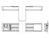
Popular
- Program for changing the angle of attack and pitch
- Actual output speed Calculation of closed gear train
- What is the procedure for the use of official transport by an employee
- aircraft fuel system
- Agreement for the evacuation of a vehicle Standard agreement for the evacuation of a vehicle
- Bulldozer performance and how to improve it Basic information about bulldozers
- Toyota Production System (TPS) and Lean Manufacturing
- Examination tickets by profession line pipe fitter
- What to do if you don't feel like doing anything
- Globus - shops for the whole family