Stand instruction manual for. test bench
Stand operation manual
1. Test for the strength and density of the material of products.
Open the valve on the fixture plug.
Install the product under test in the fixture, clamping it with the handwheel and pressing it with the clamp's hydraulic jig.
Open shutter plug
open valve
Fill the product with water until air is forced out of the plug, close the valve located on the plug of the device.
Set "Pressure 2"
After testing the product, open the valve on the plug of the device, thereby relieving the pressure to 0.
2. Seal tightness test.
Install the product under test in the fixture by tightening it
fangs and tightening the clamp with a hydraulic cylinder.
Open the shutter of the plug.
open valve
Fill the product to the shutter with water, close the shutter of the plug.
Set "Pressure 1" (working)
Bring the pressure in the system to the required value according to the technological process for testing products
After testing the product, open the shutter on the plug, thereby relieving the pressure to 0.
Press out the clamping cylinder.
Squeeze out the fangs of the device.
Rotate the item to be tested 180 degrees and repeat
trial.
Remove the tested product from the stand.
Development of a passport for the stand
Purpose
The test stand is designed to test pipeline fittings in conditions close to reality. At the stand, it is possible to test gate valves DN 80 ... 200, with water pressure up to Рр 1.4: 4; 6.3 MPa, and air pressure 0.6 MPa. The stand tests the strength and density of the material and product, as well as testing the tightness of the shutter.
Technical characteristics of the stand
1. Pressure applied on the product test stand:
a) working water ....................................................... .. 1.6; 4.0; 6.3 MPa
b) test water ............................................... ...2.4; 6.0; 9.5 MPa
c) air ............................................... .........................0.6 MPa
2. Volume of the water tank .............................................. ................90 l
3. High pressure multiplier
a) the diameter of the pneumatic cylinder .................................................... ....200 mm
b) multiplier rod diameter .........................................40 mm
c) stroke of the multiplier rod .............................................. .250 mm
d) fluid supply for 1 stroke .............................................. ........0.314 l
4. Pump for filling the product with water......................................PA-22
5. Product clamp hydraulic cylinder
a) piston diameter .............................................. ....................200 mm
b) piston stroke ............................................... ...............................40 mm
6. Hydrostation: SV-M1-40-1H-2.2-5.3
a) working pressure .............................................................. ............. 12.5 MPa
b) electric motor power .......................................................... 2.2 kW
7. Stand dimensions
a) length ............................................... ...................................3500 mm
b) width ............................................... ...............................1100 mm
c) height ............................................... .................................2000 mm
8. Weight ............................................... ...................................1700 kg
INJECTOR TESTING AND CLEANING STAND 1.0 GENERAL INFORMATION 1.1 PURPOSE OF THE MANUAL The purpose of this manual is to ensure the full and correct use of the tester and its periodic maintenance. Please read this manual carefully before using the stand. The stand is equipped with safety devices to prevent damage and loss to the user during operation. SPIN SRL is not liable in case of misuse of the stand and in case of deactivation of the security systems by the user. This symbol is used to indicate that non-observance of the instructions and rules of operation may cause harm to people. 1.2 UNIT IDENTIFICATION The bench is identified by a plate that indicates the model, production date and serial number. This plate is located on the side panel of the stand. 1.3 TECHNICAL CAPABILITIES The stand for checking and cleaning injectors allows you to test electromagnetic injectors under pressure, with display of performance in volumetric flasks, cleaning, flushing, as well as testing mechanical injectors (opening and closing pressure). 1.4 SAFETY RULES - Before working inside the booth, disconnect the power supply (mains wire) from the mains; - Work in a well-ventilated area; - Do not inhale fumes from cleaning products; - Avoid any contact of cleansing products with the skin; - Use protective gloves; - Do not leave the unit unattended during operation; - Avoid dispersion of cleaning products in the environment; - Do not work with the plexiglass cover removed. 1.5 INSTRUCTIONS FOR THE CORRECT USE OF THE STAND * The internal pump must not operate in the absence of testing liquid: there is a risk of damage to it!!! See chapter 2.3. * Do not allow the stand to operate continuously for more than 10 minutes (5 minutes if the pressure is more than 6 bar). If the pump has been running for a long time, take a break to allow the pump to cool before restarting. * The pump may be damaged due to lack of test fluid or use of ultrasonic cleaning fluid other than Spin fluid (such cases are not covered by the warranty). * Do not turn on the ultrasonic bath without liquid. * All injectors to be tested must be placed in the unit with the correct adapters and fixtures. If the injector is dropped, internal parts may be damaged. * Before turning on the pump, make sure that the pressure regulator (position 14 in figure 3) is in the leftmost position. 1.6 SAFETY DEVICES AVAILABLE IN THE STAND * Emergency stop button (red mushroom) (position 12 in Figure 3) ! Attention: Before restoring operation after an emergency stop, make sure that all switches are in the "off" position. * 12 V fuses (items 2 and 3 in figure 2), and a mains switch protective cover for 220 volts (item 4 in figure 2). The “Mastermate Evolution” unit is equipped with a pressure gauge to display the pump pressure (up to 11 bar). NOISE LEVEL The noise level of the operating unit does not exceed 80 decibels. The measurements were made with a phonometer of the 2nd class of accuracy in accordance with IEC 651, 804. 1.7 TECHNICAL CHARACTERISTICS Maximum number of simultaneously tested injectors: 6. Automatic detection of the type of injectors (high/low resistance). High pressure pump with solenoid safety valve (12bar). PURGE Frequency: 1 Hz (open and close injector valves once per second) Opening time: 450 milliseconds Procedure time: 15 minutes : 1.0 - 16.00 milliseconds Test duration: 10 - 600 seconds 2.0 INSTALLATION 2.1 Transportation The stand is delivered in a carton, the inner tank is without liquid. Only in this condition can the unit be transported. 2.2 DESCRIPTION OF THE INSTALLATION 1-5 1. Test fluid tank filter; 2. Pump fuse; 3. Fuse of the injector control board; 4. General switch and safety block (5x20 10A); 1 Fig.1 Location of the filter in the tank 3 4 2 Fig.2 Automatic fuses and general switch 5. Pump start button; 6. Wash button (lavaggio); 7. Button to turn on the preset test; 8. Button "stop" 9. Button for selecting injector testing programs; 10. Digital display; 10a. Injector testing selection activation indicator; 11. Buttons +/- to set an individual program for testing injectors (number of revolutions, injection duration); 12. Emergency stop button (red mushroom); 13. Output for connecting a stroboscope; 14. Pressure regulator; 15. Pressure gauge 0-16 bar; 16. Thermostat for adjusting the heating of the ultrasonic bath tank; 17. Timer for the duration of the ultrasonic bath (maximum 15 min. ); 18. Ultrasonic bath switch; 19. Holder for injectors with a tap; 20. Block of volumetric flasks. 6 7 8 9 10 10а 11 5 12 15 13 14 Fig.3 19 20 Fig.5 Fig.4 16 17 18 2.3 PREPARING THE UNIT FOR OPERATION A) Place the unit in a well-lit and ventilated place. B). Remove the plexiglass protection panel and fill the inner reservoir with REM 40 until the filter (1) is covered. Do not use other liquids! C) Connect the network cable to the network, and turn on the general switch (4), the built-in indicator of the switch turns on. Turn on the pump and set the pressure to 3-4 bar. Bleed air from the system, open the far left valve until all air is expelled. 2.4 PREPARATION OF THE ULTRASONIC BATH CAUTION: Do not turn on the ultrasonic bath when there is no liquid in the tank (neither bath heating nor ultrasonic emitter)! Objects that are in the ultrasonic bath must not touch the walls or the base. Avoid thermal shocks, which lead to deformation of the tank with subsequent damage to the ultrasonic transducer and heating element. Minimum level 8cm → Fig 7 ● Prepare the ultrasonic bath liquid in the ratio of 5% washing liquid 5411 and 95% water. ● Turn on the ultrasonic bath with the green switch (18), turn the thermostat switch (16) to set the tank temperature to 70°. To turn on the ultrasound, turn the timer switch (17) to the maximum (15 minutes). To remove air bubbles from the fluid in the tank, turn on the ultrasonic for 5 minutes before cleaning the injectors. The tank will be ready when air bubbles appear on the surface (maximum intensity). If there are no bubbles, just add a little water, or lower the liquid level by opening the drain cock on the side of the ultrasonic bath. ● Use the special screws in the injector holder to adjust the immersion of the injectors into the liquid. ● The ultrasonic power is highest in the center of the tank, place the injector holder in this location. ● For the use of the ultrasonic bath, please read the chapter. 3.0. ● SELECT: pressing this button allows you to select one of the 13 programs included in the installation, the display shows "P" with the serial number of the program, which can be changed using the "+" and "-" buttons. ● STOP: Pressing this button stops any setting function. 2.5 DESCRIPTION AND CHARACTERISTICS OF THE PROGRAMS If the unit is not working (all signal lights are off, there is no indication on the display), it is possible to select test programs by pressing the SELECT button (9) and select them by pressing the "+" and "-" buttons (11). Available programs: P 01; P02; P03; P04; P 05 These five programs provide the user with a choice of testing the injectors under conditions appropriate to the operating conditions of the engine at different speeds. Each program simulates different operating conditions of injectors operating at a fixed and variable number of revolutions and injection duration. P 01 - 1000 rpm (1 pulse per revolution) injection duration time 2 ms. P 02 - 2000 rpm (1 pulse per revolution) injection duration time 5 ms. P 03 - 3000 rpm (1 pulse per revolution) injection duration time 5 ms. P 04 - 4000 rpm (1 pulse per revolution) injection duration time 3 ms. P 05 - 5000 rpm (1 pulse per revolution) injection duration time 3 ms. P06; P07; P 08 These three programs allow tests to be carried out under conditions corresponding to the operating conditions of the engine at a speed of 1000-2000-3000 rpm with different injection durations. The programs can be used to compare new and old injectors with the same technical data P 06 - 1000 rpm. with the desired injection time P 07 - 2000 rpm. with the desired injection time P 08 - 3000 rpm. with desired injection time P9 This program simulates an acceleration mode of 800-5000-800 rpm, with an injection time of 3-10-3ms respectively P10 Injector static performance test, injector fully open for 15 seconds. Multiplying the liquid volume by 4, you get the static output per minute. This program is especially useful after cleaning the injectors in an ultrasonic bath. Using this program makes it possible to remove blockages from the injector and microfilter as the needle valve is open for 15 seconds. P11 This program makes it possible to set the desired injection speed and injection time by simulating various injector operating modes on the engine. Set the display to P 11, press the SELECT button again; n will appear on the display, with the arrows "+" and "-" you can increase or decrease the number of revolutions. Press the SELECT button again, d appears on the display, use the "+" and "-" arrows to change the injection time. After setting the test parameters, turn on the stand by pressing the TEST and POMPA buttons. P12 This program allows you to set the desired duration of the test. P13 Timer setting program; press the SELECT button, select program 13, then press the SELECT button. Pressing the TEST button turns on the test automatically in the preset mode. Connecting a stroboscope makes it possible to qualitatively assess the spray pattern and the degree of fuel refinement during injection. 2.6 DESCRIPTION OF THE BUTTONS ● POMPA (PUMP): Pressing this button turns on the pump. ● LAVAGGIO (FLUSHING): Pressing this button, sets an electrical signal (unchangeable) at which the injector valves are open for a long time. This allows flushing liquid to pass in large quantities through the injector valves. ● TEST: Pressing this button turns on the program previously selected in the SELECT mode; DISPLAY INDICATORS: n: number of revolutions; d: injection time; t: test duration time 2.7 LEAK TIGHTNESS CHECK ● The injectors removed from the engine are installed in the stand. When testing for leaks, always use a plexiglass cover plate. ● Without measuring flasks and with taps open, press the POMPA button, and set the pressure with the pressure regulator to 4 bar (for multiport injection systems) or 2 bar (for mono injection systems), do not press the cleaning and test buttons. To test high pressure injectors: carefully assemble adapters, do not exceed 10 bar pressure, and test within a few seconds. Check that no drops form at the end of the injectors. Reduce the pressure and turn off the POMPA (pump). If the injectors are leaking, carry out an ultrasonic cleaning followed by a check. 2.8 INJECTOR PERFORMANCE TEST Place the glass measuring flasks under the injectors and select program 2 or 3. Press the POMPA and TEST buttons, using the pressure gauge and pressure regulator, set the required pressure. This test is carried out to determine the difference in the performance of the injectors. As soon as the amount of test liquid in at least one of the measuring flasks reaches 100 ml, press the STOP button. Visually determine the difference in performance between the injectors. 2.9 INJECTOR SPRAY QUALITY TEST Select program 9, turn on the pump, connect a stroboscope and evaluate the shape of the spray pattern and the degree of fineness of the fuel by the injectors during injection. 3.0 CLEANING THE INJECTORS IN THE ULTRASONIC BATH Close the taps and remove the injectors from the unit. Remove removable elements from the injectors (rubber sealing rings, protective caps, microfilters, etc.) using a special puller (Figures 8, 9). Fig.8 Fig.9 ● Install the injectors into the special holes of the holder in the ultrasonic bath (preparation of the ultrasonic bath is described in chapter 2. 4) connect the control cables to the injectors, and press the button labeled "lavaggio" (flushing). Clean the injectors for 15 minutes at 70°C. ● Remove the injectors from the ultrasonic bath and disconnect the control cables. Connect the rubber adapters to the injectors at the outlet side, if possible (figure 10). Place the injectors into the unit with the adapters up (fig. 11) Fig. 10 Fig. 11 ● Switch on the “lavaggio” program (flushing) and perform a backwash for 1-2 minutes. ● Remove the rubber adapters from the injectors. ● Before installing spare parts (rubber sealing rings, protective caps, microfilters, etc.), test the performance of the injectors. ● Insert test flasks into the unit. ● Using program 2 or 3, check whether the performance of all injectors is the same. If the quality of the injectors is satisfactory, install new removable elements (rubber sealing rings, protective caps, microfilters, etc.). 3.1 NON-REMOVABLE INJECTORS (Fiat Uno Turbo, Alfa 75 6V) The fuel rail assembly with injectors is removed from the car, the fuel supply line is connected to one of the 6 fittings of the installation. The injectors rest on volumetric flasks. 3.2 CHECKING THE K JETRONIC INJECTORS The adapter set art. 043.3 (option) includes 6 adapters for K JETRONIC (Mercedes, Porsche) and 5 adapters for VW and Audi. Install the injectors with adapters in the installation. Turn on the pump, open the taps and watch the quality of the test liquid spray by the injectors (you can hear a characteristic trill). Set the pressure to 5 bar for 20 - 30 minutes, then reduce the pressure to 3.5 bar (at this pressure the injectors must be closed). Repeat this check several times if all injectors close at 3.5 bar all are OK. Injectors that do not close must be replaced. During the test, it is desirable to keep the taps in a half-open state. 3.3 CHECKING INJECTORS FOR SINGLE INJECTION On the stand it is possible to check and clean injectors for single injection of various types (Bosch, Weber, Ford, etc.) (adapters are supplied on request, option). It is necessary to insert and fix the tested injectors into the installation using adapters and connect the electrical cable to one of the 6 connectors using a special cable from the kit. Attention! Using the regulator (14), set the test pressure to 1 bar +/- 0.1. Check the installed injector for 5/10 minutes and evaluate the spray pattern and fineness of the fuel. If the result is not satisfactory, perform ultrasonic cleaning. 3.4 HIGH PRESSURE INJECTORS With GDI injectors it is possible to carry out the same checks as with conventional multipoint injection injectors, it is necessary to use special adapter kits (supplied on request). Attention! Test for 5 to 10 minutes, in order to avoid overheating of the pump during longer use, allow it to cool down before turning it on again. Important! When returning to normal operation, turn the pressure regulator (14) to the leftmost position and turn off the pump. Figure 12 shows an Alfa Romeo JTS injector, pressure 8 bar. Figure 12 Always test with the plexiglass shield fitted. 4.0 MAINTENANCE Test fluid tends to become contaminated with use. If dirty, replace. Before filling the tank with new fluid, thoroughly clean the inside of the tank and replace the filter located in the tank. If the pump is operated at maximum operating pressure, the fuse may trip due to the high power consumption. In any case, do not exceed the pressure of 11 bar. Periodically replace the dirty liquid in the ultrasonic bath with fresh liquid, and clean the surface with a soft cloth. If the unit is not in use for several days, empty its tanks of liquids. Before removing the liquid, make sure that the container is not heated. Avoid thermal shocks, which lead to deformation of the tank with subsequent damage to the ultrasonic transducer and heating element. 5.0 STANDARD INSTALLATION ● 6 volumetric flasks with a measuring scale, 100 cubic centimeters ● 6 holders for installing injectors with stopcocks ● 6 backwash adapters ● 6 clamps for mounting injectors ● test liquid canister for the "REM 40T" installation ● canister with liquid for ultrasonic bath “5411” ● connection cable for single injection injector ● output for connection of stroboscope 5.1 ACCESSORIES SUPPLIED ON REQUEST Adapter set for high pressure injectors art. 043.3 Adapter kits: K Jetronic for Porsche, Mercedes (6 pcs.), K Jetronic, Golf, Audi (5 pcs.), Cold start injector, Bosch mono-Jetronic mono-injection, Weber SPI mono-injection art. 043.6 Set for mono-Motronic Bosch art. 043.9 Single injection Ford Fiesta 1.1/1.3 adapters for Ford Escort XR2 (Weber MIW) art. 043.10 Extractor for K-Jetronic art. 043. 11 Adapter kit for injectors for Citroen Xantia, Peugeot, Ford Z (16V) and Bosch Y10 i.e. art. 043.8 Set of consumables for maintenance of L and K injectors 043.14 Special tool for extracting protective caps and microfilters art. 043.24 Set of adapters for petrol direct injection system injectors (GDI/FSI) art. 046/95 Stroboscope specially designed for the test set and with a special adapter. Sets of consumables (microfilters, atomizers, rubber sealing rings) The Mastermate unit has a warranty period of 12 months from the date of sale. If there is no liquid in the tank, do not turn on the ultrasonic bath (neither the bath heating nor the ultrasonic emitter). Objects that are in the cleaning tank must not touch the walls or the bottom of the tank. Avoid thermal shocks that deform the tank and damage the ultrasonic transducer and heating element. The internal pump must not run without liquid: there is a risk of damage! The warranty is not supported if the user did not adhere to this manual or neglected the safety rules described in it during the use of the installation. DECLARATION OF CONFORMITY with the requirements of E.S. SPIN srl, Via Consolare 15, Rimini (Italy), hereby declares under its own responsibility: The “MASTERMATE EVOLUTION” test rig, serial no. subsequent amendments 89/392 CEE 91/368 CEE 93/44 CEE 93/68 CEE LOW VOLTAGE DIRECTIVE and subsequent amendments 73/23 CEE 93/68 CEE ELECTROMAGNETIC COMPATIBILITY DIRECTIVE and subsequent amendments 89/336 CEE 93/68 CEE Regulations on circulation: EN 60204-1; EN 50081-1; EN 50082-1 Legal representative Ing. Fokki Marco ____________________
SCIENTIFIC AND PRODUCTION COMPANY "META"
APPROVE
CEO
OOO NPF "Meta"
N.V. Martynov
"____" _____________ 2012
STANDS BRAKE
STM 16000.02
Manual
M 059.000.00.00-01 RE
INTRODUCTION 5
1 DESCRIPTION AND OPERATION 5
1.1 Description and operation of the product 5
1.1.1 Purpose 5
1.1.2 Specifications 6
1.1.3 Product composition 7
1.1.4 Design and operation 7
1.1.5 Marking and sealing 24
1.1.6 Packaging 24
2 INTENDED USE 25
2.1 Operating restrictions 25
2.2 Preparing the product for use 25
2.3 Using the product 26
2.4 Functional monitoring procedure, regulation and adjustment 29
2.5 Dealing with extreme conditions 39
3 MAINTENANCE 40
3.1 Product maintenance 40
Maintenance 42
STORAGE 45
TRANSPORTATION 45
Appendix A Assembly diagram of STM 16000.02 assembly 46
The operating manual for the STM 16000.02 brake stand (hereinafter referred to as the stand) is intended to study the device and the principle of operation of the stand and contain the information necessary for its proper operation and maintenance.
Personnel who have studied the technical documentation, have undergone training and preliminary safety briefing are allowed to work at the stand.
Maintenance, preventive maintenance and repair of the stand is allowed to personnel who have studied the technical documentation and have a safety qualification group of at least the third.
The stand is repaired by the manufacturer.
The current working program of the stand is posted on the website of the manufacturer www. meta- en. en .
1 DESCRIPTION AND OPERATION
1.1 Description and operation of the product
1.1.1 Purpose
STM brake stands (hereinafter referred to as the device) are designed to test the braking systems of vehicles (TS), control the braking efficiency and stability of vehicles during braking in accordance with the requirements of GOST R 51709 “Motor vehicles. Technical Condition Requirements and Verification Methods” and Order of the Ministry of Industry and Trade of the Russian Federation dated December 6, 2011 N 1677 “On approval of the main technical characteristics of technical diagnostic tools and their list”;
Stands brake STM are intended for measurements:
braking force developed by the braking systems of vehicles;
the mass attributable to the axle of vehicles;
efforts applied to the controls of the brake systems of vehicles;
The stand is intended for operation in the allocated territories of motor transport enterprises and service stations, the electrical networks of which are not connected to the networks of residential buildings.
Type of climatic modification - U2 in accordance with GOST 15150-69.
In terms of resistance to mechanical stress - the stand is of ordinary design according to GOST R 52931.
The stand complies with all requirements ensuring consumer safety in accordance with GOST 26104, GOST 12.2.007.0.
1.1.2 Specifications
| Name | Meaning |
| Brake force measurement range, kN Relative error limit of braking force measurements, %, no more | from 0 to 40 ±3 |
| Measurement range of the force applied to the controls of the brake systems, N Limit of relative measurement error of the force applied to the brake system controls, %, not more than | from 0 to 1000 |
| Weight measurement range, kg Relative error limit of mass measurements, %, no more | from 0 to 16000 ±3 |
| Power consumed by the stand, kW, no more | 16 |
| Parameters of a four-wire three-phase power supply network with permissible deviations in accordance with GOST 12 997-84 Voltage, V, frequency Hz | 380 +10% -15% |
| Time to establish the operating mode, min, no more | 15 |
| Stand continuous operation time, h, not less | 8 |
| Overall dimensions, mm, no more | 2010x800x440 |
| - control cabinet | 550x460x120 |
| Weight, kg, no more Support roller device Control cabinet | |
| Operating temperature range of the supporting roller device, o С | -10+40 |
| Average service life, years, not less | 8 |
| Mean time between failures, h, not less than | 6000 |
| Average recovery time, h, no more | 6,4 |
Note - * - weight of each supporting roller device
The operation of the stand is controlled from the keyboard of a personal computer.
Commands to the operator are displayed on the monitor screen and duplicated on a traffic light or remote display, supplied by an additional order.
The roller drive is switched off when the set value of the slip coefficient between the wheels of the tested vehicle and the drive rollers is reached.
The stand provides the output of measurement results and service information to the printing device.
The stand provides the possibility of self-departure of the car after the check.
1.1.3 Product composition
1.1.3.1 The composition and scope of delivery corresponds to Table 1.
Table 1
| Name | Designation | Qty, pcs. | Note |
| Support roller device | 2 | ||
| Control cabinet | M 259.500.00 | 1 | |
| Traffic lights | 1 | ||
| force sensor | M 016.100.00-03 | 1 | |
| PC system unit Minimum requirements: Case, 300-350 W, ATX “InWin” (335x450x550) mm | 1 1 | ||
| Intel chipset motherboard with integrated video | 1 | ||
| Celeron min 2GHz | 1 | ||
| DVD-R drive | 1 | ||
| HDD (HDD) min 80Gb | 1 | ||
| RAM 256 Mb DDR | 2 | ||
| Monitor Samsung TFT19” 923 NW | 1 | ||
| PS/2 keyboard | 1 | rus/lat |
|
| a printer | 1 | by order |
|
| Optical mouse | 1 | ||
| STM USB adapter | M 041.700.00 | 1 | |
| Cable set | 1 | ||
| Lever arm | M 059.020.00.00 B | 1 | by order |
| Loading device for verification of weight sensors | M 059.030.00.00 A | 1 | by order |
| Force-giving device | M 016.950.00 | 1 | by order |
| Retainer | M 020.205.00.00 | 2 | |
| Breather plug | M 020.114.00.19 | 2 | |
| Cargo bracket | M 141.100.90.00 | 4 | |
| The passport | M 059.000.00.00-01 PS | 1 | |
| Manual | M 059.000.00.00-01 RE | 1 | |
| Verification procedure | 1 | ||
| Installation instructions | 1 |
Notes
1 Additionally, on request, a radio remote control, an information board, a foundation frame and a dynamometer-attachment "DP-020", a stand for a PC and software "Diagnostic control" can be supplied.
When equipped with a control rack, the Sunc Master 710N monitor is supplied
(LCD 17").
1.1.4 Design and operation
1.1.4.1 Principle of operation and arrangement of the stand.
The stand refers to roller stands of a power type, the operation of which is based on the principle of measuring the braking force transmitted from the wheels of the car through the support rollers to the balancing electric motor and perceived by the strain gauge, followed by processing the results on a personal computer and displaying them on the monitor screen and printing device.
The stand consists of two modules of supporting roller devices (hereinafter referred to as the roller unit) for the left and right wheels, a control cabinet, a PC, a printer, a traffic light or an information board and a force sensor.
The roller unit measures the mass of the diagnosed axle and sets the wheels of this axle in motion to measure the braking force.
The composition of the roller installation (Fig. 1 and Fig. 2) includes:
* motor - reducer;
* two support rollers;
* tracking roller;
* four weight sensors;
* brake force sensor;
* vehicle presence sensor;
* slip sensor;
* sensor controller (only for the left roller installation).
Legend:
DV-1….DV-8 – weight sensors
DTS-L, DTS-P - left and right brake force sensors
DN-L, DN-P - left and right vehicle presence sensors
DPR-L, DPR-P - left and right slip sensors
Figure 1 - Functional diagram of the stand STM 16000.02

2010
1-Base; 2-roller brake; 3-Drive; 4-Power converter; 5-roller tracking; 6-Slip sensor; 7-Collision sensor; 8-Weight sensor
Picture 2 - Support roller devices (roller installation)
All units of roller installations can be mounted on a welded rectangular frame with ramps for independent entry and exit of the vehicle onto the roller installation or on a frame - a foundation frame mounted on the basis of an inspection pit. Roller installations for both the right and left wheels are installed in the frame on supports - weight sensors and are kept from shifting by two clamps.
Weight sensors are designed to convert the mass of the diagnosed axle into an electrical signal. Geared motors drive the support rollers onto which the vehicle drives. When braking, reactive moments from the geared motors are transmitted to the brake force sensors, which generate electrical signals proportional to the braking forces of the right and left wheels.
Between each pair of support rollers there are follower rollers, with which vehicle presence sensors and slip sensors are connected, designed to control the speed of rotation of the wheels and determine the moment when the wheels of the diagnosed axle begin to slip relative to the support rollers, as well as to determine the presence of a car on the support rollers of the roller installation.
The sensor controller is designed to convert and amplify sensor signals, convert analog sensor signals into a digital code and transfer their values to a personal computer upon its request.
1.1.4.2 The control cabinet (Fig. 3, 3a) is designed to accommodate elements of power electroautomatics. It consists of:
* residual current device (RCD);
* automatic switches;
* set of connectors for connection to:
force sensor;
To the traffic light
To the roller installation;
to the switch;
To control buttons;
To USB adapter;
* PC ground terminal;
* block combined;
* block of clamps.
The electrical equipment of the stand is connected to the network by a residual current device RCD. When the START button is pressed, the relay contacts are closed, and a voltage of ± 12 V is supplied to the stand controller input.
When the STOP button is pressed, the relay contacts open.
The control of the inclusion of motor-reducers is carried out from the USB adapter of the brake tester, which is connected to the USB port of a personal computer.
The electrical equipment of the control cabinet is disconnected from the mains using the mushroom-shaped emergency shutdown button or by turning off the MAINS voltage switch.
Protection against overloads and short circuits in the power supply circuits of motor-reducers is carried out by automatic switches.
Note– When operating the brake tester as part of a mobile diagnostic station, use the power cabinet of the station.

Figure 3 - External view of the control cabinet

1-Pulse power supply; 2-Switch NETWORK; 3-Differential RCD switch; 4-automatic switch ENGINE LEFT; 5-Automatic switch ENGINE RIGHT; 6-Block combined; 7.8-solid-state relay; 9-Zero tire; 10-block of clamps; 11-Connector for connecting the force sensor; 12- Connector for connecting a traffic light; 13-Connector for connecting the STM controller; 14- Connector for connecting the switch; 15-Signal cable; 16-Bracket with START and STOP control buttons
Figure 3a - Location of control cabinet elements
Force sensor on the control
The force sensor (Fig. 4) is designed to measure the force on the controls of the working and parking brake systems. Consists of housing 1, top plate 2, bottom plate 3, button 4, sensor cable 5 with connector 6. Inside the housing there is a strain gauge bridge and permanent magnets used to attach the sensor to the brake pedal using a coercive force generated by permanent magnets. The sensor connector is connected to the counterpart located on the control cabinet. When checking the parking brake system, the force sensor is fixed to the hand brake using a dynamometer attachment (see Fig. 2, Appendix A).

1- Housing; 2- Top plate; 3- Bottom plate; 4- Button; 5-Sensor cable; 6-Sensor connector
Figure 4 - Force sensor
1.1.4.4 Traffic light and information board
The traffic light and the information board are designed to display commands to the operator who checks the vehicle during the operation of the brake tester.
The traffic light consists of three signal lamps (red, yellow, green). Combinations of turning on these lamps depending on the operator's commands are shown in Table 2.
The information board displays commands to the vehicle operator in the form of text messages.
table 2
| Command to the operator - driver | The color of the traffic lights on |
| GREEN and RED |
|
| STANDBY mode | GREEN, RED and YELLOW |
| Mode Spare brake system | RED and YELLOW in 1 second GREEN and YELLOW |
| ENTER OR EXIT | GREEN |
| BRAKES SMOOTHLY | RED |
| GET READY (in departure mode) | YELLOW |
| Release the pedal and wait for the command | None of the lights are on |
1.1.4.5 PC system unit
The system unit of a personal computer is connected to a USB adapter, through which the brake tester motor-reducers are controlled and information is received from the sensor controller about the current values of the brake tester sensor signals. The control and communication lines are galvanically separated from the PC circuits.
Attention! The socket block to which the computer and printer are connected must be connected to a 220 V 50 Hz network separately from the 3-phase power network.
1.1.4.6 Bench operation
Checking the condition of the brake system of the car is carried out by two operators. The operator-driver is located at the driver's seat of the vehicle being checked. The PC operator directs the actions of the operator-driver. Commands to the operator-driver are displayed on the monitor screen, and are also duplicated at a traffic light or information board. The stand allows to measure the full range of parameters of the vehicle's braking system by sequentially moving all vehicle axles to the roller installations of the stand and measuring all the parameters of each diagnosed axle in accordance with the instructions of the working program and the instructions of the PC operator. The brake forces are measured on the surface of the wheels and are measured in kilonewtons (kN).
The principle of operation of the stand consists in the forced rotation of the wheels of the diagnosed axle of the car from the support rollers and the measurement of the forces arising on the surface of the support rollers during braking. After the axle being diagnosed enters the roller installations and when the left and right vehicle presence sensors are triggered, the axle is weighed using weight sensors.
Then the support rollers of the roller installations are put into rotation. Rotation occurs at a given speed from the motor - reducers.
The reactive torques that occur during braking are transmitted to sensors that generate electrical signals proportional to the braking forces on each pair of rollers. The rotation of the vehicle wheels is transmitted to the follower rollers, which are pressed against the wheels of the axle being diagnosed. The rotation speed of the follower rollers is controlled by slip sensors. The moment of the beginning of the impact on the brake pedal is fixed by a button located on the force sensor, which is also designed to determine the force on the brake pedal.
The signals from all sensors are sent to the sensor controller located on the left roller unit. The sensor signals are amplified to the required value by precision amplifiers, converted into a digital code by an analog-to-digital converter and fed to the microprocessor, which pre-processes the incoming information. Upon request from a personal computer, the microprocessor transmits complete information about the state of the brake tester sensors.
Communication between the personal computer and the sensor controller is carried out by a USB adapter connected to the system unit of the personal computer. The USB-adapter also controls the operation of motor-reducers and traffic lights. Devices are installed on the USB adapter that provide galvanic isolation along the control lines of the traffic light and motor-reducers, as well as along the lines of communication with the sensor controller.
The personal computer controls the operation of the traffic light and the information board, which displays the commands of the PC operator to the operator-driver.
On the power panel of the control cabinet there are elements of power automation that implement the algorithm of the stand. Switching on and control of motor-reducers is carried out by solid-state reversing relays.
The control of the inclusion of traffic light lamps is carried out by signals from opto-triacs.
The transformer is designed to power the low-voltage components of the stand.
Voltages from its output windings are rectified by diode bridges, smoothed and fed to integrated voltage stabilizers, at the output of which stabilized DC voltages "+12 V" and "-12 V" are formed.
1.1.4.7 Bench control program
This program contains all the information necessary for the user to work with the STM stand.
The first chapter deals with the main window of the program.
The second chapter contains a detailed description of typical user operations.
Email: teh-avto@yandex.ru, ICQ: 7-585-777
TIN 7606064703, checkpoint 760601001, account 40702810100000005364
in OJSC "YARSOTSBANK", Yaroslavl, c/c 30101810300000000773
BIK 047888773, OKPO 81920811
BRAKE STAND modular UNIVERSAL
STM - 15000U
Manual
M 059.000.00.00 RE
The operating manual for the STM-15000U modular universal braking stand (hereinafter referred to as the stand) is intended to study the device and the principle of operation of the stand and contain the information necessary for its proper operation and maintenance.
Personnel who have studied the technical documentation, have undergone training and preliminary safety briefing are allowed to work at the stand.
Maintenance, preventive maintenance and repair of the stand is allowed to personnel who have studied the technical documentation and have a safety qualification group of at least the third.
The stand is repaired by the manufacturer.
DESCRIPTION AND OPERATION
Description and operation of the product
1.1.1 Purpose
The stand is designed to control the braking efficiency and stability of motor vehicles (ATS) during braking, including cars, trucks, buses, as well as multi-axle and all-wheel drive vehicles with an axle load of up to 15,000 kg.
Stands can be used at state technical inspection stations of vehicles, service stations, automotive industry enterprises to monitor the effectiveness of vehicle brake systems in operation, when released on the line, as well as during annual technical inspection.
The stand provides determination of the following braking efficiency parameters:
Mass of the diagnosed axle;
Effort on the governing body;
Specific braking force;
Relative difference in braking forces of one axle;
Response time of the brake system;
Ovality of the wheels of the diagnosed axle.
To control cars that do not have a differential between the driving axles, the stand ensures the rotation of the left and right wheels in different directions.
The stand is intended for operation in the allocated territories of motor transport enterprises and service stations, the electrical networks of which are not connected to the networks of residential buildings.
Type of climatic modification - U2 in accordance with GOST 15150-69.
In terms of resistance to mechanical stress - the stand is ordinary in accordance with GOST 12997-84.
The stand complies with all requirements ensuring consumer safety in accordance with GOST 26104, GOST 12.2.007.0.
1.1.2 Specifications
1.1.2.1 Main technical data:
Initial braking speed, simulated on the bench, km/h 20.1
Brake force measurement range on each wheel of the tested axle, kN
STM-15000U 0 - 40
STM-15000U.01 0 - 30
Measuring range of the force generated on the organ
Brake system control, N 0-1000
Limit of permissible reduced error, % ± 5
Axle mass measurement range, kg 0-15000
Limit of permissible reduced error, % ± 3
Operating time measuring range
brake system, sec 0-1.5
Parameters of a four-wire three-phase power supply network with permissible deviations in accordance with GOST 12 997-84
Voltage, V 380 +10 - 15
Frequency, Hz 50 + 1
Power consumption, no more, kVA 16.0
Overall dimensions, no more than, mm
Roller unit module 2010x810x415
Control stand 650 x 1200 x 680
Traffic light 70 x 200 x 200
Weight, no more than, kg
Roller unit 650
Control post 50
Traffic light 5
Vehicle track width, mm from 900 to 3100
Operating mode establishment time, min, no more than 15
Stand continuous operation time, h, not less than 8
Average service life of the stand, not less than, years 8
Working temperature range, С -30+50
* Note: According to GOST R51709-2001 "Motor vehicles. Requirements for technical condition and verification methods" introduced from 01.01.2002. the braking efficiency parameter "Brake system response time" is excluded from the list of normalized metrological characteristics and is a reference characteristic of brake systems.
1.1.2.1 Main specifications
The operation of the stand is controlled from the keyboard of a personal computer.
Commands to the operator are displayed on the monitor screen and duplicated on a traffic light or remote display, supplied by an additional order.
The roller drive is switched off when the set value of the slip coefficient between the wheels of the tested vehicle and the drive rollers is reached.
The stand provides the output of measurement results and service information to the printing device.
The stand provides the possibility of self-departure of the car after the check.
1.1.3 Product composition
1.1.3.1 The composition and scope of delivery corresponds to Table 1.
Table 1
| Name | Designation | Qty, pcs. | Note |
| Roller module | M 059.100.00.00 | 2 | |
| Control desk | M 131.900.00 | 1 | |
| Traffic lights | M 024.43.100 | 1 | |
| Tripod for traffic lights | M 020.300.10 | 1 | |
| force sensor | M 016.100.00 | 1 | |
| PC system unit | 1 | Minimum Requirements: no worse than Intel 486DX2-100MHz, RAM-32Mb, HDD-2.5Gb, Floppy-1.44Mb, graphics card-PCI/SVGA 1Mb, Windows 95, mouse, 14" monitor. Supply: Intel Pentium compatible at least 500 MHz, RAM-64Mb, HDD-at least 10Gb, Floppy-1.44Mb, video card-AGP 4Mb, Windows 98, mouse, 15" monitor. |
|
| PC monitor | 1 | SVGA color |
|
| PC keyboard | 1 | rus/lat |
|
| trackball | 1 | ||
| TC USB adapter | M 041.700.00 | 1 | |
| Cable set | 1 | ||
| Lever arm | M 059.020.00.00 | 1 | |
| Loading device for verification of weight sensors | M 059.030.00.00 A | 1 | by order |
| Force-giving device | M 016.950.00 | 1 | by order |
| Dynamometer-attachment "DP-20" | M 020.041.00.00 | 1 | by order |
| a printer | 1 | by order |
|
| The passport | M 059.000.00.00 PS | 1 | |
| Manual | M 059.000.00.00 RE | 1 | |
| Verification procedure | M 059.000.00.00 DL | 1 | |
| Installation instructions | М 059.000.00.00 IM | 1 |
1.1.4 Design and operation
1.1.4.1 Principle of operation and arrangement of the stand.
The stand refers to roller stands of a power type, the operation of which is based on the principle of measuring the braking force transmitted from the wheels of the car through the support rollers to the balancing electric motor and perceived by the strain gauge, followed by processing the results on a personal computer and displaying them on the monitor screen and printing device.
The stand consists of two modules of a roller installation for the left and right wheels, a control rack containing a PC and power electrical elements (power panel), a traffic light or an information board and a force sensor.
The roller unit measures the mass of the diagnosed axle and sets the wheels of this axle in motion to measure the braking force.
The composition of the roller installation (Fig. 1 and Fig. 2) includes:
* motor - reducer;
* two support rollers;
* tracking roller;
* four weight sensors;
* brake force sensor;
* vehicle presence sensor;
* slip sensor;
* sensor controller (only for the left roller installation).
All units of roller installations can be mounted on a welded rectangular frame with ramps for independent entry and exit of the vehicle onto the roller installation or on a frame - a foundation frame mounted on the basis of an inspection pit. Roller installations, both for the right and for the left wheel, are installed in the frame on supports - weight sensors and are kept from displacement by two clamps.
Weight sensors are designed to convert the mass of the diagnosed axle into an electrical signal. Geared motors drive the support rollers onto which the vehicle drives. When braking, reactive moments from the geared motors are transmitted to the brake force sensors, which generate electrical signals proportional to the braking forces of the right and left wheels.
Between each pair of support rollers there are follower rollers, with which vehicle presence sensors and slip sensors are connected, designed to control the speed of rotation of the wheels and determine the moment when the wheels of the diagnosed axle begin to slip relative to the support rollers, as well as to determine the presence of a car on the support rollers of the roller installation.
The sensor controller is designed to convert and amplify sensor signals, convert analog sensor signals into a digital code and transfer their values to a personal computer upon its request.
1.1.4.2 Power panel (Fig. 3c and 3d) is designed to accommodate elements of power electroautomatics. It consists of:
* Releaser;
* Automatic differential switch with residual current device (RCD);
* Automatic phase switch;
*Set of connectors for connection to:
force sensor;
To the traffic light
To the roller installation;
to the switch;
To control buttons;
To USB adapter;
* PC ground terminal;
* Block combined;
The electrical equipment of the stand is connected to the network by a magnetic starter. When the START button is pressed, the starter is turned on, self-blocking and, with its main contacts, connects the electrical equipment of the power cabinet to the network.
The control of the inclusion of motor-reducers is carried out from the USB adapter of the brake tester, which is connected to the USB port of a personal computer.
To protect against switching interference, RC circuits are used, connected in parallel with the starter coils (they are part of the combined unit).
When the STOP button is pressed, the starter is switched off.
The electrical equipment of the power panel is disconnected from the network.
Protection against overloads and short circuits in the power supply circuits of motor-reducers is carried out by a thermal relay.
The power panel is located on the middle shelf of the control rack behind the printer.
Note - When operating the brake tester as part of a mobile diagnostic station, use the power cabinet of the station.
A connector is installed on the bracket on the lower shelf of the control rack, through which 220 V voltage is supplied to power the PC.
The horizontal position of the control rack is adjusted by screws located at the base of the rack.
Before checking the brake system of the car, the sensor is fixed with a belt 8 on the brake pedal of the car. The sensor connector is connected to the counterpart located on the power cabinet.
1.1.4.4 Traffic light and information board
The traffic light and the information board are designed to display commands to the operator who checks the vehicle during the operation of the brake tester.
The traffic light consists of three signal lamps (red, yellow, green). Combinations of turning on these lamps depending on the operator's commands are shown in Table 2.
The information board displays commands to the vehicle operator in the form of text messages.
table 2
| Command to the operator - driver | The color of the traffic lights on |
| GREEN and YELLOW |
|
| EMERGENCY BRAKING mode | RED and YELLOW |
| GREEN and RED |
|
| STANDBY mode | GREEN, RED and YELLOW |
| Mode Spare brake system | RED and YELLOW in 1 second GREEN and YELLOW |
| ENTER OR EXIT | GREEN |
| BRAKING HARD (in emergency braking mode) BRAKING SMOOTHLY (in all other modes) | RED |
| HOLD (in emergency braking mode) GET READY (in departure mode) | YELLOW |
| Release the pedal and wait for the command | None of the lights are on |
1.1.4.5 PC system unit
The system unit of a personal computer is connected to a USB adapter, through which the brake tester motor-reducers are controlled and information is received from the sensor controller about the current values of the brake tester sensor signals. The control and communication lines are galvanically separated from the PC circuits.
Attention! The socket block to which the computer and printer are connected must be connected to a 220 V 50 Hz network separately from the 3-phase power network.
1.1.4.6 Bench operation
Checking the condition of the brake system of the car is carried out by two operators. The operator-driver is located at the driver's seat of the vehicle being checked. The PC operator directs the actions of the operator-driver. Commands to the operator-driver are displayed on the monitor screen, and are also duplicated at a traffic light or information board. The stand allows to measure the full range of parameters of the vehicle's braking system by sequentially moving all vehicle axles to the roller installations of the stand and measuring all the parameters of each diagnosed axle in accordance with the instructions of the working program and the instructions of the PC operator. The brake forces are measured on the surface of the wheels and are measured in kilonewtons (kN).
The principle of operation of the stand consists in the forced rotation of the wheels of the diagnosed axle of the car from the support rollers and the measurement of the forces arising on the surface of the support rollers during braking. After the axle being diagnosed enters the roller installations and when the left and right vehicle presence sensors are triggered, the axle is weighed using weight sensors.
Then the support rollers of the roller installations are put into rotation. Rotation occurs at a given speed from the motor - reducers. The reactive torques that occur during braking are transmitted to sensors that generate electrical signals proportional to the braking forces on each pair of rollers. The rotation of the vehicle wheels is transmitted to the follower rollers, which are pressed against the wheels of the axle being diagnosed. The rotation speed of the follower rollers is controlled by slip sensors. The moment of the beginning of the impact on the brake pedal is fixed by a button located on the force sensor, which is also designed to determine the force on the brake pedal.
The signals from all sensors are sent to the sensor controller located on the left roller unit. The sensor signals are amplified to the required value by precision amplifiers, converted into a digital code by an analog-to-digital converter and fed to the microprocessor, which pre-processes the incoming information. Upon request from a personal computer, the microprocessor transmits complete information about the state of the brake tester sensors.
Communication between the personal computer and the sensor controller is carried out by a USB adapter connected to the system unit of the personal computer. The USB-adapter also controls the operation of motor-reducers and traffic lights. Devices are installed on the USB adapter that provide galvanic isolation along the control lines of the traffic light and motor-reducers, as well as along the lines of communication with the sensor controller.
The personal computer controls the operation of the traffic light and the information board, which displays the commands of the PC operator to the operator-driver.
In the power cabinet there are elements of power automation that implement the algorithm of the stand. The control signals for turning on the motor-reducers are fed to transistor current switches, in the collector circuits of which electromagnetic relays are switched on that control the magnetic starters of the motor-reducers.
The control signals for turning on traffic lights are also fed to transistor current switches, in the collector circuits of which electromagnetic relays are switched on that control the turning on of traffic lights.
The transformer is designed to power the low-voltage components of the stand.
Voltages from its output windings are rectified by diode bridges, smoothed and fed to integrated voltage stabilizers, at the output of which stabilized DC voltages "+12v" and "-12v" are formed.
1.1.4.7 Bench control program
This program contains all the information necessary for the user to work with the STM stand.
The first chapter deals with the main window of the program.
The second chapter contains a detailed description of typical user operations.
transcript
1 Test bench KS-3 Operation manual
2 CONTENTS 1. INTRODUCTION Purpose of the document Description of the device Safety information Specification Pneumatic circuit Equipment of the stand Diagram of external connections of the stand KC Stand options ) 9.3. Filter (T) Bench modifications No pressure gauges (NPG) Vacuum adjustment (B) Operating instructions Basic information about using the bench Connecting the bench to a pressure source Preparing for calibration/verification Calibration/verification Residual pressure ventilation Disconnecting the bench from the pressure source Preparing for calibration/verification electrocontact pressure gauges Preparing for calibration / verification of pressure sensors Replacing the filter Maintenance... 12
3 1. INTRODUCTION Dear customer! Thank you for purchasing the test bench KS-3 of the TEK-Tech trademark and trusting in our company. We hope that you will be able to convince yourself of the reliability of our product. The device is made of high quality materials and has passed comprehensive control. Before starting work, we ask you to carefully read this manual and follow the recommendations indicated in it for the correct, efficient and safe use of the stand. The instructions in the operating manual will help you quickly get used to the device and use it efficiently from the first minutes. We wish you successful use of the test stand KS-3! 2. Purpose of the Document This Operation Manual explains how to use the KC-3 stand correctly and safely. You can use this manual to solve all kinds of issues related to the use of the KC-3 stand. Always keep this manual in the same place. This manual has been developed to familiarize users with the main features of the stand. Attention! This test bench is designed for precise adjustment of pressure and vacuum using the built-in volume regulator when checking and calibrating pressure gauges, pressure sensors and other pressure measuring instruments. The stand is designed for precision pressure setting in manual mode. It is unacceptable to use this stand for any other types of work. The manufacturer is not responsible for malfunctions and breakdowns that occurred in case of using the stand for other purposes, as well as in case of improper or unreasonable use. The manufacturer is not responsible for typographical errors or errors in copying this manual. We reserve the right to make changes to the device that, in our opinion, are necessary or useful and do not affect the main characteristics of the device. 3. Device Description The KC-3 stand is designed for fine manual pressure adjustment. Its feature is the presence of a pressure regulator for quick initial pressure adjustment (coarse), as well as a volume regulator for fine adjustment. Built-in dial gauges allow you to control the supply pressure and the pressure adjusted by the regulator. The balancing valve, located in front of the volume regulator, allows you to set the initial pressure in both chambers of the regulator. This reduces the force required to turn the volume control knob and reduces wear. The extended base of the stand provides comfort and stability during use. 3
4 The KC-3 stand can be equipped with two to five outlet ports, with the ability to turn them off (using a shut-off valve). The stand can be equipped with a module for checking electrocontact pressure gauges and (or) a module for switching the output signal and power supply (24V) of pressure sensors. Thanks to 180/250*/330*mm spacing between output ports, instruments of any size can be installed on the stand. The stand can be equipped with a particulate and oil filter. *as requested by the customer 4. Safety information Please read the operating instructions of the device before using it. Use this device only for its intended use. Improper use of the device presents dangers to people and other equipment. The device may only be operated by qualified personnel who are fully familiar with the device. General Warnings Before using the device and its accessories, inspect them for any visible damage that may have occurred during shipping. Do not attempt to connect, mount or remove the device while the system is under pressure. The operating pressure of the device must not exceed the specified one. Electrical Warnings To avoid electrical shock or damage to the instrument, do not connect more than 30 V between the terminals or between the terminals and ground. Pneumatic Warnings Compressed gases and liquids are dangerous! Depressurize the machine before connecting or disconnecting equipment. Before connecting, make sure all accessories are pressure rated, safe to use, and securely attached. 4
5 5. Specification Pneumatic connections - outlet Pneumatic connections inlet Operating pressure for test stand KC-3 2, 4 or 5 1-in closed (pressure) bar bar bar 0-17 bar 0-35 bar 0-55 bar bar bar Supply pressure Operating temperature Relative humidity Internal volume of the volume regulator Number of turns of the volume regulator Pneumatic connection threads Dimensions (Length x Width x Height) Possibility of installing a module for checking electrocontact pressure gauges (EK) bar +5 o C to 35 o C 80 % at 25 o C 13.5 cm 34 GPV-M20 570/780/960(750/960/1140)* x 300 x 240 mm Yes Possibility to install a power supply module (24 V) and switch the output signal Also available pressure sensors (K) Possibility to install a particulate filter and oil * Stand length with filter Yes 3 5
6 6. Pneumatic diagram Fig. Pneumatic diagram KC volume regulator 2 - equalization valve 3 - pressure regulator filling valve connection - pressure inlet 6 - connection - outlet 7 - outlet valve A - system pressure gauge B - supply pressure gauge Fig Pneumatic diagram KC- 3-T 1 - volume regulator 2 - equalization valve 3 - pressure regulator filling valve connection - pressure inlet 6 - connection - outlet 7 - outlet valve 8 - filter 9 - relief valve A - system pressure gauge B - supply pressure gauge Figure Pneumatic diagram KC-3B 1 - volume regulator 2 - equalization valve 3 - pressure regulator pressure filling valve vacuum filling valve connection - pressure inlet connection - vacuum inlet 6 - connection - outlet 7 - outlet valve 6
7 7. Stand equipment Pic. 7.1 Components and mechanisms of the stand KC-34-EK-К-T-GPV-M20: 1 - volume regulator; 2 - equalization valve; 3 - pressure regulator; filling valve; pressure connection - inlet; 6 - connections; 7 - outlet valve; 8 - filter; 9 - relief valve; A - pressure gauge in the system; B - supply pressure gauge; C - switch of the module for verification of pressure sensors; D - toggle switch for switching measurements. 7
8 8. Scheme of external connections of the KC-3 bench 9. Bench options 9.1 Module for verification of electrocontact pressure gauges and pressure switches (EK) 9.2 Module for power supply (24 V) and switching the output signal of pressure sensors (K) 9.3. Filter (T) The stand can be ordered with additional options: a module for checking electrocontact pressure gauges and pressure switches, a power supply module (24 V) and switching the output signal and powering pressure sensors. The stand can be equipped with a module for checking electrocontact pressure gauges and pressure switches. Such a stand is additionally equipped with LED indicators for each checked pressure gauge or pressure switch, one sound signal for all checked devices and one 24 V power supply. The stand can be equipped with a power supply module (24 V) and switching the output signal of pressure sensors. Such a stand is additionally equipped with a circuit that provides continuous verification of all calibrated pressure sensors in turn, a 24 V power supply and LED indicators for each calibrated pressure sensor. Channel switching can be controlled both manually and with the help of a PC. The stand can be equipped with a particulate and oil filter. The filter is installed outside, which makes it easy to replace the filter elements. 8
9 10. Stand modifications No pressure gauges (NPG) Vacuum adjustment (B) At the request and choice of the customer, the stand can be manufactured with various modifications. The stand can be made without pressure gauges designed to monitor the pressure in the system and the supplied pressure. The stand can be a pressure and vacuum regulator. Possible pressure range and number of outlets are shown in table 10.2 Table Pneumatic connections inlet -0.9* barg -0.9* - 3.5barg -0.9* barg * depends on the vacuum pump 11. Operating Instructions 11.1 Basic information about using the test bench The test bench KS-3 is equipped with a pressure regulator 3 (Figure 7.1) for coarse pressure adjustment and a volume regulator 1 (Figure 7.1) for fine adjustment. For both of these devices, the pressure is increased by turning the knob clockwise and decreased by turning it counterclockwise. NOTE: as a safety precaution, it is recommended to set the pressure regulator to its minimum setting after each use! Stand KS-3 has a built-in equalization valve 2 (Figure 7.1). This valve, located in front of the volume regulator, allows you to set the initial pressure in both chambers of the regulator. This reduces the force required to turn the Volume Control Knob 1 and reduces wear. By closing equalization valve 2, the volume of the system decreases. NOTE: It is not recommended to change the system pressure using a pressure regulator while the balancing valve is closed! Standaks-3 has a pressure filling valve 4.1 (Figure 7.1). When the bench is not in use, the system is separated from the pressure source by turning the pressure filling valve 4.1 all the way, counterclockwise. The stand is equipped with two manometers*. Pressure gauge "A" (Figure 7.1) is designed to monitor the pressure in the pressure source. "B" (figure 7.1) to monitor the pressure in the system. * At the request of the manufacturer, the stand can be made without pressure gauges. nine
10 11.2 Connecting the bench to the pressure source 11.3 Preparing for calibration/verification Inspect the bench and pressure hose for damage. Make sure the pressure source does not exceed 172 bar. Make sure filling valve 4.1 (Figure 7.1) is CLOSED. Make sure pressure regulator 3 (Figure 7.1) is set to MINIMUM. Make sure equalization valve 2 (Figure 7.1) is OPEN. Connect the pressure source to the stand. Perform the "Connecting the stand to the pressure source" procedure, if it has not already been done before. Make sure all outlet valves 7 are OPEN. Connect an external reference pressure gauge. Connect a pressure gauge to be verified. Close unused output ports. Make sure the pressure source does not exceed 172 bar, OPEN its valve. Slowly OPEN the filling pressure valve 4.1. The pressure gauge in system "A" should show what pressure the pressure source has. Using pressure regulator 3 and observing system pressure “A”, INCREASE system pressure to the desired maximum calibration/verification point. CLOSE equalization valve 2. Observe the reference gauge to verify that there is no leakage of system pressure (slight fluctuation in system pressure may be due to thermodynamic processes). OPEN equalization valve 2. If calibration/verification is performed from a low point, use the pressure or vacuum supply valve to set the desired minimum pressure. Calibration/verification 1. Perform the “prepare for calibration/verification” procedure if it has not been done before. 2. Make sure equalization valve 2 is OPEN. 3. Watching the pressure in the "A" system, and turning the pressure regulator 3 to the right, SET the required pressure. 4. CLOSE equalization valve Using volume regulator 1, set the desired pressure. 6. Record instrument readings. 7. OPEN equalization valve If there are additional calibration/verification points, repeat steps 2-7, Section 10.4 calibration/verification. Note: to reduce ventilation and gas consumption from the pressure source, change the calibration/verification points sequentially by increasing and decreasing the pressure. 10
11 11.5 Residual pressure ventilation Make sure that the fill valve 4.1 is CLOSED. Make sure equalization valve 2 is OPEN. Set the pressure regulator 3 to the MINIMUM value (all the way to the left). Turn off external pressure gauges. Pressurize the system using pressure regulator 3 to decrease the inlet line pressure. Set pressure regulator 3 to the MINIMUM value Disconnecting the bench from the pressure source Ensure that the pressure source is CLOSED, pressure regulator 3 is set to the MINIMUM value. Open filling valve 4.1. Make sure equalization valve 2 is OPEN. Pressurize the system using pressure regulator 3 to decrease the inlet line pressure. Set pressure regulator 3 to MINIMUM. Disconnect the stand from the pressure source Preparation for calibration/verification of electrocontact pressure gauges Follow the procedure “connecting the stand to the pressure source” P.11.2, if it has not been performed before. Connect an external reference pressure gauge (pressure calibrator). Connect a verified electrocontact pressure gauge. Attach the red and black wires to the pressure gauge electrical contacts. Turn on the electrical contact verification module C (figure 7.2). Make sure the pressure source does not exceed 172 bar, OPEN its valve. Check the pressure gauge according to the procedure for checking electrocontact pressure gauges Preparing for calibration / verification of pressure sensors Perform the procedure “connecting the stand to the pressure source” P.11.2, if it has not been completed before. Connect an external reference pressure gauge (pressure calibrator). Connect the pressure sensor to be tested. Attach the red and black wires to the power supply of the pressure sensor. Fasten the wires as indicated in the diagram (Figure 11.8). Switch toggle switch D to position, depending on whether you want to measure current in manual mode, voltage in manual mode, or current/voltage via PC (RS232). Turn on the pressure sensor verification module C. Depending on the output signal pressure transducers (from 0 to 5 mA, 0-20 mA, 4-20 mA), use the toggle switch (on the case) to select the required load (500 Ohm, 1200 Ohm) of the circuit. The load value is determined by the method of verification of pressure transducers. Connect the stand to the device that reads the data. Verify according to the procedure for checking pressure sensors. eleven
12 Fig Connection diagram of pressure sensors 11.9 Replacing the filter The bench can be equipped with a filter against solid oil particles. The filter is installed outside, which makes it easy to replace the filter elements. Use the relief valve 9 (Figure 7.1) to release the condensate from the filter. From the underside of the filter, loosen the pipe adapter and unscrew the filter housing. Unscrew the filter element retainer, change the element and screw the retainer. Screw on the filter housing and tighten the pipe adapter. 12. Maintenance A quick visual inspection of the device should be carried out before each use. Parts subject to wear should be replaced every 5 years. The maintenance period also depends on the different circumstances in which the device is used and should be reduced if the installation is operated under extreme conditions. All parts can be replaced with original or recommended by the manufacturer. 12
Test stand KS-2 Operation manual CONTENTS 1. INTRODUCTION 2. Purpose of the document 3. Device description 4. Safety information 5. Specification 6. Pneumatic scheme 7.
Test bench KS-5 Operation manual CONTENTS 1. INTRODUCTION .......... 3 2. Purpose of the document ...... 3 3. Description of the device ...... 3 4. Safety information ...... 4 5. Specification.........
Test stand KS-4 Operation manual CONTENTS 1. INTRODUCTION 2. Purpose of the document 3. Device description 4. Safety information 5. Specification 6. Pneumatic scheme 7.
Test bench KC-3 Contents 1. Description of the device... 3 2. Specification... 4 3. Pneumatic diagrams... 5 4. Equipment of the bench... 6 5. Diagram of external connections of the KC-3 bench... 7 6. Stand options...
Test stand KS-3 DESCRIPTION CONTENTS 1. Description of the device... 3 2. Specification... 3 3. Pneumatic diagrams... 4 4. Equipment of the stand... 5 5. Scheme of external connections of the stand KS-3... 6 6. Options
Test stand KS-5 DESCRIPTION Contents 1. Description of the device...... 3 2. Specification.................. 4 3. Pneumatic schemes...... 4 4. Equipment of the stand. ..... 6 5. Scheme of external connections of the stand
Test stand KS-2 DESCRIPTION CONTENTS 1. Description of the device... 3 2. Specification... 3 3. Pneumatic diagrams... 4 4. Equipment of the stand... 5 5. Scheme of external connections of the stand KS-2... 6 6. Options
Operation Manual KS-4 Pneumatic Stand Table of Contents 1. Product Description...3 2. Specification...3 3. Pneumatic Diagrams...4 4. Operation Manual...6 5. Maintenance...7
NUFORS-CR Installation and Maintenance Manual Pneumatic Condensate Trap 3/2018 GENERAL INSTRUCTIONS FOR USE The NUFORS-CR Pneumatic Steam Trap removes condensate from the compressed air system.
Installation and Maintenance Manual 1 02-2018 SAFETY AND PROPER USE
Pressure switching kit 0-16 bar Wilo pressure switching kit ER-2 Pressure sensor kit (4-20mA) WMS kit 1 Contents: 1. General...3 1.1. Purpose...3 2. Technique
EN Automation kit with hydraulic accumulator for submersible vibration pump AQUAROBOT M Installation and operation manual EN This manual contains fundamental instructions that should
Installation and Maintenance Manual STEAM TAP HEATER Automatic Thermograph 7/16 GENERAL INSTRUCTIONS FOR USE During the winter season or when a level-sensitive steam trap is installed
Precision pressure controller DPI 515 Purpose: Maintaining the pressure of a given value, calibrating and checking pressure measuring instruments. Accuracy: ±0.01% F.S. Stability: 0.001% F.S.
Installation and Maintenance Manual ACD-TEC-COMBO Timer Controlled Steam Trap 02/18 The ACD-TEC-COMBO Timer Controlled Steam Trap consists of an electronic timer controlled
AUTOMATIC VOLTAGE REGULATOR SE350 INSTRUCTION MANUAL (DETAIL DESCRIPTION, INSTALLATION AND ADJUSTMENT) INTRODUCTION SE350 is a thyristor-type half-wave phase controlled voltage regulator. He
Installation and Maintenance Manual ACD-TEC-HP40 Timer Controlled Steam Trap Basic Information 02/18 ACD-TEC-HP40 removes condensate from compressed air equipment using a solenoid
Portable pressure calibrators and precision digital manometers DPI 610/DPI 615 Measurement ranges: - pressure from 0...70 to 0 700 kgf/cm 2 ; - pressure-vacuum from ±0.0025 to -1...35 kgf/cm2
DK10-03.06.03 INSTALLATION MANUAL AND USER MANUAL Thermostat Model KFC-11 Contents 1. Introduction...3 2. Operating environment...3 3. Precautions...4 4. Installation...5 5. Description
Operating manual for electronic pressure regulators models: EDD-5, EDD-1, EDD-3, EDD 2-R, EDD-12-R, EDD-AS Thank you for purchasing our brand product! We guarantee you high quality and
KIT 07 OPERATING MANUAL PLEASE READ THE OPERATING REQUIREMENTS SET FORTH IN THIS MANUAL CAREFULLY BEFORE USING THE EQUIPMENT. TO OBTAIN INFORMATION ABOUT THE APPLICATION
INSULATION RESISTANCE METER HDT-2048 INSTRUCTION MANUAL Dear user! Thank you for choosing the HDT-2048 from our Insulation Resistance Tester range. For safe and
METROL 212 Manual pneumatic pump Passport Operating manual The operating manual is intended for specialists and trained employees. Before each work step, carefully
HEATERS Series Series...U Electric duct heater Electric duct heater with power from 0.0 kW to 1.0 kW with control module Electric duct heater with power from 0.0
Thank you for your purchase! Cable tester MASTECH MS-6813 PRECAUTIONS page 1 of 6 To avoid possible electric shock and personal injury: Use the tester only as directed
LPA-DUO-MIC Microphone Console with Zone Selector Operating Instructions Version 1.1 www.luis-lpa.com Thank you for purchasing LPA brand equipment. The information provided in this guide
0 Frying top EG-730 G/EC These operating instructions contain technical specifications, information about the design of the equipment, operation of the equipment, as well as safety precautions
Ver. 2 1 CONTENTS PURPOSE... 3 FILTER PARTS... 4 CONSUMABLES... 4 TECHNICAL SPECIFICATIONS... 5 ASSEMBLING AND INSTALLING THE FILTER... 6 PRESSURE ADJUSTMENT... 6 AUTOMATIC CONDENSATE DRAIN...
Four Common PRESSURE CALIBRATION ISSUES Calibrating pressure gauges is often critical to the operation of process control systems. It helps streamline workflows
Contents--- Warnings 1 Safety Instructions 1 Important Notes 1 Features 1 Front Panel Controls 2 Rear Panel Controls 2 Connection
Contents 1 Purpose.... 2 2 Specifications.... 2 3 Scope of delivery.... 2 4 Design of the device and principle of operation.... 3 5 Safety precautions.... 5 6 Preparation for operation.... 6 7 How to use....
Power Supply Instruction Manual Model (0-30V-30A), (0-60V-30A) with 2 LCD Screens General Description Thank you for purchasing this DC power supply. In order to use it correctly,
R O T H E N B E R G E R ELECTRIC PRESS PUMP RP PRO II OPERATING INSTRUCTIONS 1 2 3 Specifications: Voltage: 220-240V, 50 Hz (110V), single phase Nom. engine power:
ELECTRIC BOILER WITH WATER JACKET CONTENTS: Models Nameplate and packaging Wiring diagram Important information INSTALLATION, USE AND CARE INSTRUCTIONS l. INSTALLATION INSTRUCTIONS
HEATERS Series Duct electric heater Application Duct electric heaters are designed for supply air heating in rectangular ventilation systems. Apply
VOLTAGE REGULATOR RENAP-1D Technical description and operating instructions 2 1. INTRODUCTION This technical description and operating instructions apply to AC regulators
Power Supply Instruction Manual Model QJ3003C III (0-30V-3Ax2;5V/3A), (0-30V-5Ax2;5V/3A), (0-50V-3Ax2;5V/3A) General Description Thank you for purchasing QJ3003C III, constant power supplies
BAU - 80B AUTOMATIC CONTROL UNIT Attention! Dear buyer! When buying an automatic control unit: (Models: BAU - 80B) require checking its performance by a test run and checking
RMC 45, RMC 55, RMC 60, RMC 70, RMC 75, RMC 80, RMC 85 Instantaneous water heaters (pressure)
LABORATORY SWITCHING DC POWER SUPPLY MEGEON 30ХХХ Operation manual and passport 1 INTRODUCTION Unpacking the power supply: The power supply is sent to the consumer by the manufacturer
WWW.VIVA-TELECOM.RU 1 Contents Instructions for safety and general use Specifications Front control panel Rear control panel System connections Specification
UPS Battery Pack Operation Manual SIPB 1~3K BA UPS floor standing models with output power factor 0.8 July 2015 version 1.2 CONTENTS 1. Introduction... 3 2. Safety...
1. PURPOSE. The Aiken automation unit of models Mip-44 (Fig. 1), Mip-45 (Fig. 2) (automatic device) allows you to automate the operation of the electric pump, starting with a decrease in pressure (opening taps)
Switching Power Supply Instruction Manual Model PS3010 (0-30V-10A), 1 LCD Screen General Description Thank you for purchasing the PS3010 Switching DC Power Supply. In order for him
DK16-03.06.01 INSTALLATION MANUAL AND USER MANUAL Thermostat MODEL: KFC-15 Contents 1. Precautions...3 2. Operating environment...3 3. Functionality...3 4. Installation...4
Contents 1. Introduction...4 2. Verification operations...4 3. Means of verification...5 4. Safety requirements ......5 5. Verification conditions and preparation for it.......... .5 6. Carrying out verification......5 7. Determination of metrological
TOTO GIOVANNONI SERIES Washlet TCF892G/GE WASHLET Installation Manual Warnings and Cautions 2 Before Installing the Washlet 3 Product Contents 4 Parts 5 Meaning of Symbols
Operating instructions for the pneumohydraulic pump art. D104736 INTENDED PURPOSE Pneumohydraulic pump Trommelberg with foot control for work with stocks, hydraulic extensions and other devices.
SWIMMING POOL PUMPS INSTRUCTIONS MD SERIES JA SERIES PRECAUTIONS When installing and operating this electrical equipment, always follow the basic precautions: 1.
Nitrogen Tire Inflator Model DS-130 Instruction Manual Please read this instruction manual carefully before performing commissioning and maintenance work.
SmartK12 12 Channel LED Dimmer User Manual 1 No part of this manual may be reproduced in any form or by any means without written permission from
Regulated power supply instruction manual, models (0-30V-3A), (0-30V-5A), QJ5003C (0-50V-3A) 2 LCD screens
AUTOMOBILE COMPRESSOR 13.61 CONTENTS Purpose of the product...2 Scope of delivery...3 Main technical characteristics...4 Design of the product...5 Preparation for operation...6 Recommendations for care and maintenance...8
IP Bogdanov Andrey Alexandrovich, Krasnodar MUSIDORA (R) Digital-to-analogue converter DMX512 to analog signal 0..+10V (PWM) Operation manual TECHNICAL CHARACTERISTICS Operating voltage:
Industrial Sewing Machine Servomotor User Manual Thank you for purchasing our product. For your safety, please read the manual before use. save
Contents Cautions 1 Safety Instructions 1 Functional Specifications 1 Front Panel Controls 2 Rear Panel Controls 2 Connecting the System 3 Specifications
LIMITED LIABILITY COMPANY "EKOPROMKONTROL" SCHSU-P BOARD OF THE STATION FOR AUTOMATIC CONTROL OF THE ELECTRIC DRIVE OF THE PUMPING UNIT ON THE BASIS OF A FREQUENCY CONVERTER OPERATING INSTRUCTIONS
Operating instructions Mechatronic flow sensor SBG33x 704758/01 03/011 Contents 1 Safety instructions... Proper use...3 3 Installation...3 4 Electrical
ENGINE DOES NOT START First of all, specify the circumstances of the malfunction, analyze the general condition of the car. Check that the vehicle is filled with the correct quality fuel and oil?
A set of amplifiers for transmitting a video signal of black and white and color images over a twisted pair of a multi-core cable TWIST-MINI PASSPORT 1 Purpose A set of amplifiers for transmitting a video signal TWIST-MINI
APPROVED by the General Director of O O O N P L "^ ^ APPROVED by the Deputy Director for Production Metrology of the Federal State Unitary Enterprise VNIIMS Okladnikov Ivannikova 2017 PNEUMATIC PRESSURE CALIBRATORS "ELEM ER-P
DKPP 33.20.51.750 CO 2 TEMPERATURE AND CONCENTRATION RECORDER LT-2-14 (LOGGER) Operation manual AAEI.405516.017 RE Contents Introduction... 4 1 DESCRIPTION AND OPERATION... 4 1.1 Purpose... 4 1.2
UPS Battery Pack Instruction Manual SIBP 1~3K KA Rack Mount UPS Models with Output Power Factor 0.8 July 2015 Version 1.2 CONTENTS 1. Introduction... 3 2. Safety...
Installation and Operation Instructions Contents SAFETY AND PRECAUTIONS 3 PRODUCT DESCRIPTION 4 PRODUCT CODES 4 APPLICATIONS 4 TECHNICAL DATA 4 STANDARDS 5 PERFORMANCE DIAGRAM 5 CONNECTION
Vacuum Cleaner ZODIAC T5 DUO Operating Instructions This appliance has been designed, manufactured and tested with the utmost care to ensure that you are completely satisfied with the product. Before use
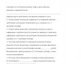


Popular
- Drinking water bottling business
- Sales agent job description
- Ready-made business plan for opening an insurance agency from scratch
- How can I open an IP for apartment renovation?
- Statistical reporting 1 type annual deadline
- How small business reports to Rosstat
- What new business ideas have appeared in Russia from Europe and the USA (America)?
- Features of the production of plastic bags
- Foreign trade balance (trade balance) How is a country's foreign trade balance measured?
- Ready business plan for a beauty salon