Analysis of the nature and consequences of fmea failures. Use of Markov Chains to Calculate Reliability Indicators of Systems with Recovery
To deal with the second part, I strongly recommend that you first familiarize yourself with.
Failure Modes and Effects Analysis (FMEA)
Failure Mode and Effect Analysis (FMEA) is an inductive reasoning-based risk assessment tool that considers risk as a product of the following components:
- the severity of the consequences of a potential failure (S)
- the possibility of a potential failure (O)
- probability of failure to be detected (D)
The risk assessment process consists of:
Assigning to each of the above risk components an appropriate level of risk (high, medium or low); with detailed practical and theoretical information on the principles of design and operation of the qualified device, it is possible to objectively assign risk levels for both the possibility of failure and the probability of failure to be detected. The possibility of a failure can be viewed as the time interval between occurrences of the same failure.
The assignment of risk levels for the probability of failure to be detected requires knowledge of how the failure of a particular instrument function will occur. For example, failure of the system software assumes that the spectrophotometer is unusable. Such a failure can be easily detected and therefore assigned a low level of risk. But the error in measuring the optical density cannot be detected in a timely manner, if the calibration has not been performed; accordingly, the failure of the function of the spectrophotometer for measuring the optical density should be assigned a high level of risk of its non-detection.
The assignment of a risk severity level is a somewhat more subjective process and depends to some extent on the requirements of the respective laboratory. In this case, the level of risk severity is considered as a combination of:
Some suggested criteria for assigning a risk level for all the components of the cumulative risk assessment discussed above are presented in Table 2. The proposed criteria are most suitable for use in a regulated product quality control environment. Other laboratory analysis applications may require a different set of assignment criteria. For example, the impact of any refusal on the quality of a forensic laboratory may ultimately affect the outcome of a criminal trial.
Table 2: proposed criteria for assigning risk levels
| Risk level | Quality (Q) | Compliance (C) | Business (B) | Probability of occurrence (P) | Probability of non-detection (D) |
| Severity | |||||
| High | Is likely to harm the consumer | Will lead to product recall | Downtime for more than one week or potential major loss of income | More than once in three months | Hardly detectable in most cases |
| Average | Probably won't harm the consumer | Will result in a warning letter | Downtime up to one week or potential substantial loss of income | Once every three to twelve months | Can be detected in some cases |
| Short | Will not harm the consumer | Will lead to the discovery of a nonconformity during the audit | Downtime up to one day or insignificant loss of income | Once every one to three years | Probably to be discovered |
Taken from the source
The calculation of the level of aggregate risk assumes:
- Assigning a numerical value to each level of severity of risk for each individual category of severity, as shown in Table 3
- Summing the numerical values of the severity levels for each risk category will give a cumulative quantitative level of severity in the range from 3 to 9
- The cumulative quantitative level of severity can be converted to the cumulative qualitative level of severity, as shown in Table 4.
| Table 3: assignment of a quantitative level of severity | Table 4: calculating the cumulative level of severity | |||
| Qualitative level of severity | Quantitative level of severity | Cumulative quantitative level of severity | Aggregate quality level of severity | |
| High | 3 | 7-9 | High | |
| Average | 2 | 5-6 | Average | |
| Short | 1 | 3-4 | Short | |
- As a result of multiplying the cumulative quality level of Severity (S) by the level of the possibility of Occurrence (O), we obtain the Risk Class, as shown in table 5.
- The Risk Factor can then be calculated by multiplying the Risk Class by the Non-Detectability, as shown in Table 6.
| Table 5: risk class calculation | Table 6: calculation of the risk level | |||||||
| Severity level | Undetectability | |||||||
| Spawn rate | Short | Average | High | Risk class | Short | Average | High | |
| High | Average | High | High | High | Average | High | High | |
| Average | Short | Average | High | Average | Short | Average | High | |
| Short | Short | Short | Average | Short | Short | Short | Average | |
| Risk class = Severity level * Occurrence rate | Risk factor = Risk class * Level of undetectability | |||||||
An important feature of this approach is that when calculating the Risk Factor, this calculation gives additional weight to the factors of occurrence and detectability. For example, if the failure is of a high severity, but it is unlikely and easy to detect, then the overall risk factor will be low. Conversely, where the potential severity is low, but the occurrence of failure is likely to be frequent and difficult to detect, the cumulative risk factor will be high.
Thus, the severity, which is often difficult or even impossible to minimize, will not affect the overall risk associated with a particular functional failure. Whereas appearance and undetectability, which are easier to minimize, have a greater impact on the overall risk.
Discussion
The risk assessment process consists of four main stages, as follows:
- Conducting an assessment in the absence of any mitigation tools or procedures
- Establishment of means and procedures for minimizing the assessed risk based on the results of the assessment performed
- Carrying out a risk assessment after the implementation of mitigation measures to determine their effectiveness
- Establish additional mitigation tools and procedures as needed, and re-evaluate
The risk assessment, summarized in Table 7 and discussed below, is viewed from the perspective of the pharmaceutical and related industries. Despite this, similar processes can be applied to any other sector of the economy, however, if other priorities are applied, other, but no less reasonable, conclusions can be obtained.
Initial assessment
It starts with the performance functions of the spectrophotometer: wavelength accuracy and precision, as well as the spectral resolution of the spectrophotometer, which determine its suitability for authenticity testing within the UV / VIS spectrum. Any inaccuracies, lack of precision in the wavelength of determination, or insufficient resolution of the spectrophotometer can lead to erroneous results of the authenticity test.
In turn, this can lead to the release of products with unreliable authenticity, up to their receipt by the end consumer. It can also lead to the need for product recalls and subsequent significant costs or loss of income. Therefore, in each severity category, these functions will pose a high level of risk.
Table 7: risk assessment using FMEA for UV / B spectrophotometer
| Pre-minimization | Subsequent minimization | |||||||||||||
| Severity | Severity | |||||||||||||
| Functions | Q | C | B | S | O | D | RF | Q | C | B | S | O | D | RF |
| Work functions | ||||||||||||||
| Wavelength accuracy | V | V | V | V | WITH | V | V | V | V | V | V | N | N | N |
| Wavelength reproducibility | V | V | V | V | WITH | V | V | V | V | V | V | N | N | N |
| Spectral resolution | V | V | V | V | WITH | V | V | V | V | V | V | N | N | N |
| Diffused light | V | V | V | V | WITH | V | V | V | V | V | V | N | N | N |
| Photometric stability | V | V | V | V | V | V | V | V | V | V | V | N | N | N |
| Photometric noise | V | V | V | V | V | V | V | V | V | V | V | N | N | N |
| Spectral baseline flatness | V | V | V | V | V | V | V | V | V | V | V | N | N | N |
| Photometric accuracy | V | V | V | V | V | V | V | V | V | V | V | N | N | N |
| Functions to ensure data quality and integrity | ||||||||||||||
| Access controls | V | V | V | V | N | N | N | V | V | V | V | N | N | N |
| Electronic signatures | V | V | V | V | N | N | N | V | V | V | V | N | N | N |
| Password controls | V | V | V | V | N | N | N | V | V | V | V | N | N | N |
| Data security | V | V | V | V | N | N | N | V | V | V | V | N | N | N |
| Audit log | V | V | V | V | N | N | N | V | V | V | V | N | N | N |
| Time stamps | V | V | V | V | N | N | N | V | V | V | V | N | N | N |
B = High, M = Medium, L = Low
Q = Quality, C = Compliance, B = Business, S = Severity, O = Occurrence, D = Non-detectability, RF = Risk Factor
Analyzing further, scattered light affects the correctness of optical density measurements. Modern instruments can take it into account and make an appropriate correction in the calculations, but this requires that this scattered light be detected and stored in the operating software of the spectrophotometer. Any inaccuracies in the stored scattered light parameters will result in incorrect absorbance measurements with the same consequences for photometric stability, noise, baseline accuracy and flatness as described in the following paragraph. Therefore, in each severity category, these functions will pose a high level of risk. The accuracy and precision of wavelength, resolution and scattered light are highly dependent on the optical properties of the spectrophotometer. Modern diode array devices have no moving parts and therefore failures in these functions can be assigned a medium chance of occurrence. However, in the absence of special checks, failure of these functions is unlikely to be detected, therefore, undetectability is assigned a high level of risk.
Photometric stability, noise and accuracy, and flatness of the baseline affect correct absorbance measurements. If the spectrophotometer is used for quantitative measurements, any error in the absorbance measurements may result in erroneous results being reported. If the reported results from these measurements are used to place a batch of a pharmaceutical product on the market, this could result in substandard batches of the product to end users.
Such series will have to be withdrawn, which in turn will entail significant costs or loss of income. Therefore, in each severity category, these functions will pose a high level of risk. In addition, these functions are dependent on the quality of the UV lamp. UV lamps have a typical life of approximately 1500 hours or 9 weeks of continuous use. Accordingly, these data indicate a high risk of failure. In addition, in the absence of any precautions, failure of any of these functions is unlikely to be detected, which implies a high undetectability factor.
Returning now to the data quality and integrity functions, the test results are used to make decisions about the suitability of a pharmaceutical product for its intended use. Any compromise on the correctness or integrity of the records generated could potentially lead to the placing on the market of products of undetermined quality, which could harm the end consumer, and the products may have to be recalled, resulting in great losses to the laboratory / company. Therefore, in each severity category, these functions will pose a high level of risk. However, once the required instrument software configuration has been properly configured, it is unlikely that these functions will fail. In addition, any failure can be detected in a timely manner.
For instance:
- Providing access only to authorized persons to the relevant work program until it is opened, it can be implemented by prompting the system to enter a username and password. If this function fails, the system will no longer ask you to enter a username and password, respectively, it will be immediately detected. Therefore, the risk of not detecting this failure will be low.
- When a file to be verified is created electronic signature, then a dialog box opens, which requires you to enter a username and password, respectively, if a system failure occurs, then this window will not open and this failure will be immediately detected.
Minimization
While the severity of failure of operational functions cannot be minimized, the potential for failure can be significantly reduced and the likelihood of detecting such failure can be increased. Before using the device for the first time, it is recommended to qualify the following functions:
- wavelength precision and precision
- spectral resolution
- diffused light
- photometric accuracy, stability and noise
- the flatness of the spectral baseline,
and then re-qualify at specified intervals, as this will significantly reduce the likelihood and likelihood of any failure being detected. Since photometric stability, noise and accuracy, and baseline flatness are dependent on the condition of the UV lamp, and standard deuterium lamps have a lifespan of approximately 1500 hours (9 weeks) of continuous use, it is recommended that the operating procedure be specified that the lamp (s) should be turned off when the spectrophotometer is idle, that is, when it is not in use. It is also recommended that preventive maintenance (PM) be performed every six months, including lamp replacement and re-qualification (PC).
The rationale for a re-qualification period depends on the life of the standard UV lamp. It is approximately 185 weeks when used for 8 hours once a week, and the corresponding life in weeks is shown in Table 8. Thus, if the spectrophotometer is used four to five days a week, the UV lamp will last about eight to ten months.
Table 8: the average life of the UV lamp depending on the average number of eight-hour working days of the spectrophotometer during the week
| Average number of days of operation per week | Average lamp life (weeks) |
| 7 | 26 |
| 6 | 31 |
| 5 | 37 |
| 4 | 46 |
| 3 | 62 |
| 2 | 92 |
| 1 | 185 |
Every six months a prophylactic Maintenance and re-qualification (PTO / PC) will ensure trouble-free operation of the device. If the spectrophotometer is operated for six to seven days a week, the lamp life is expected to be about six months, so it is more appropriate to perform a PT / PC every three months to ensure adequate uptime. Conversely, if the spectrophotometer is used once or twice a week, then the PTO / PC will be sufficient every 12 months.
In addition, due to the relatively short service life of the deuterium lamp, it is recommended to check the following parameters, preferably on every day of use of the spectrophotometer, as this will provide an additional guarantee of its correct functioning:
- lamp brightness
- dark current
- calibration of deuterium emission lines at wavelengths of 486 and 656.1 nm
- filter and shutter speed
- photometric noise
- spectral baseline flatness
- transient photometric noise
Modern instruments already contain these tests within their software and they can be performed by selecting the appropriate function. If any of the tests fail, with the exception of the dark current and filter and shutter speed test, the deuterium lamp must be replaced. If the dark current or filter and shutter speed test fails, the spectrophotometer should not be used and should be sent for repair and re-qualification instead. Establishing these procedures will minimize both the risk of failure of a work function and the risk of failure to detect any failure.
Risk factors for data quality and integrity functions are already low without any minimization. Therefore, it is only necessary to verify the operation of these functions during OQ and PQ to confirm the correct configuration. After that, any failure can be detected in a timely manner. However, personnel must receive appropriate training or instruction to be able to recognize a failure and take appropriate action.
Conclusion
Failure Modes and Effects Analysis (FMEA) is an easy-to-use risk assessment tool that can be easily applied to assess the risks of laboratory equipment failure that affect quality, compliance and business. Performing such a risk assessment will enable informed decisions to be made regarding the implementation of appropriate controls and procedures to cost-effectively manage the risks associated with the failure of critical instrument functions.
Analysis of the types and consequences of failures of components of the technical and functional structures of the designed system is the first stage of the design study of reliability and safety. The generally accepted international abbreviation for failure mode and effect analysis is FMEA. This type of analysis belongs to the class of preliminary qualitative and simplified quantitative analysis at the design stage. If quantitative assessments are carried out, then the term FMECA (failure mode, effect and criticality analysis) is used. The first experiments in conducting FMEA refer to aerospace projects of the 60s of the USSR and the USA. In the 1980s, FMEA procedures began to be implemented in the US auto industry at the Ford Motor Company. At present, the analysis of the types and consequences of failures is a mandatory step. project appraisal reliability and safety of objects of space, aircraft building, nuclear, chemical-technological, gas-oil refining and other industries. In areas where this stage is not mandatory, dangerous incidents occur, leading to large economic and environmental losses and threatening human life and health. Suffice it to recall the dramatic events of the collapse of public Moscow buildings, built according to projects, where a defect in only one element of the supporting structure (pin, column) led to disastrous consequences.
There are three main goals of FMEA
- identification of potential types of failures of system components and determination of their impact on the system as a whole and possibly environment
- classification of failure modes by levels of severity or by levels of severity and frequency of occurrence (FMECA)
- issuing recommendations for revising design solutions in order to compensate or eliminate dangerous types of failures
FMEA is the most standardized area of "robustness" research. The procedure and type of input / output documentation is regulated by the relevant standards. Internationally recognized documents are:
· MIL-STD-1629 Style FMECAs - guidance on analyzing the modes and consequences of failures, assessing criticality, identifying bottlenecks in structures in terms of maintainability and survivability. It was originally focused on military applications.
· SAE J1739, AIG-FMEA3, FORD FMEA - a package of documents regulating the analysis of the types and consequences of failures for the objects of the automotive industry, including the design and manufacturing stages
· SAE ARP5580 - An FMEA guide for both commercial and military projects, integrating MIL-STD-1629 and automotive standards. The concept of groups of equivalent failures is introduced, i.e. failures that have the same consequences and require the same corrective actions.
Common to all standards is that they only regulate the sequence and interconnection of the stages of analysis, leaving the designer freedom of action in the specific implementation of each stage. Thus, it is allowed to customize the structure of FMEA tables, determine the scales of failure rates and the severity of consequences, introduce additional indicators for the classification of failures, etc.
FMEA steps:
Construction and analysis of the functional and / or technical structures of the object
Analysis of the operating conditions of the facility
Analysis of failure mechanisms of elements, criteria and types of failures
Classification (list) of possible consequences of failures
· analysis possible ways prevention (decrease in frequency) of allocated failures (failure consequences)
Technical structure the object of analysis usually has a tree-like, hierarchical representation (Fig. 3). Potential failure modes are listed for components lower level(tree leaves), and their consequences are assessed in terms of the impact on the subsystems next level(parent tree nodes) and the object as a whole.
Fig. 3. Hierarchical representation of the object of analysis
Figure 4. shows a fragment of the FMEA table containing data on the analysis of the types and consequences of equipment failures at a chemical technological facility.
Fig. 4. Fragment of the FMEA table.
When performing quantitative assessments of design solutions for FMEA types component failures are usually characterized by three parameters: frequency of occurrence, degree of detection, severity of consequences. Since the analysis is preliminary in nature, expert points' estimates of these parameters are usually used. For example, a number of documents propose the following classifications of failure modes by frequency (Table 2), by degree of detection (Table 3), by severity of consequences (Table 4).
Table 2. Classification of failures by frequency.
Each main component of the system is studied in order to determine the ways of its transition to an emergency state. The analysis is predominantly qualitative and is carried out according to the “bottom-up” principle, provided that emergency conditions appear “one at a time”.
Analysis of types, consequences and criticality of failures is significantly more detailed than analysis using a "fault tree", since all possible types of failures are identified or emergency situations for each element of the system.
For example, a relay can fail for the following reasons:
- contacts did not open or closed;
- delay in closing or opening contacts;
- short circuit of contacts to the case, power supply, between contacts and in control circuits;
- contact bounce (unstable contact);
- contact arc, noise generation;
- winding rupture;
- short circuit of the winding;
- low or high winding resistance;
- overheating of the winding.
For each type of failure, the consequences are analyzed, methods for eliminating or compensating for failures are outlined, and a list of necessary checks is drawn up.
For example, for tanks, containers, pipelines, this list may be as follows:
- variable parameters (flow rate, quantity, temperature, pressure, saturation, etc.);
- systems (heating, cooling, power supply, control, etc.);
- special conditions (maintenance, switching on, switching off, replacing content, etc.);
- change in conditions or condition (too large, too small, water hammer, sediment, immiscibility, vibration, rupture, leakage, etc.).
The forms of documents used in the analysis are similar to those used in the preliminary hazard analysis, but to a large extent they are detailed.
Criticality analysis provides for the classification of each element in accordance with the degree of its influence on the performance of the overall task by the system. Severity categories are established for different types refusals:
The method does not provide a quantitative assessment of the possible consequences or damage, but allows to answer the following questions:
- which of the elements should be subjected to detailed analysis in order to exclude hazards leading to accidents;
- which element requires special attention in the production process;
- what are the standards for incoming inspection;
- where special procedures, safety rules and other protective measures should be introduced;
- how to spend money most effectively to prevent
accidents.
7.3.3. Analysis of the diagram of all possible
consequences of failure or failure of the system
("Fault tree")
This method of analysis is a combination of quantitative and qualitative techniques for identifying conditions and factors that can lead to an undesirable event ("summit event"). The conditions and factors taken into account line up in a graphic chain. Starting from the top, the causes or emergency conditions of the next, lower functional levels of the system are identified. Many factors are analyzed, including human interactions and physical phenomena.
Attention is focused on those effects of a fault or accident that are directly related to the apex of the events. The method is especially useful for analyzing systems with many areas of contact and interactions.
The presentation of an event in the form of a graphical diagram leads to the fact that one can easily understand the behavior of the system and the behavior of the factors included in it. Due to the cumbersomeness of the "trees", their processing may require the use of computer systems. Due to its cumbersomeness, it is also difficult to check the "fault tree".
The method is primarily used in risk assessment to assess the probabilities or frequencies of faults and accidents. Clause 7.4 gives a more detailed description of the method.
7.3.4. Analysis of the diagram of possible consequences of an event
("Event tree")
"Event tree" (DS) - an algorithm for considering events emanating from the main event (emergency). DS is used to determine and analyze the sequence (options) of the development of an accident, including complex interactions between technical safety systems. The probability of each emergency scenario is calculated by multiplying the probability of the main event by the probability of the final event. Direct logic is used in its construction. All values of the probability of failure-free operation P are very small. The tree does not provide numerical solutions.
Example 7.1. Suppose, by performing a preliminary hazard analysis (PAO), it was revealed that the critical part of the reactor, that is, the subsystem from which the risk begins, is the reactor cooling system; thus, the analysis begins by looking at the sequence of possible events since the breakdown of the refrigeration pipeline, called an initiating event, the probability of which is P (A)(Fig. 7.1), i.e. an accident begins with the destruction (breakdown) of the pipeline - an event A.
Further, possible scenarios for the development of events are analyzed ( B,C, D and E), which may follow the destruction of the pipeline. In fig. 7.1 depicts a "tree initiating events»Displaying all possible alternatives.
The first branch examines the state of the electrical power supply. If power is available, the next to be analyzed is the emergency reactor core cooling system (ARCS). Failure of ASOR leads to fuel melting and to various, depending on the integrity of the structure, leaks of radioactive products.
For analysis using a binary system in which elements either perform their functions or fail, the number of potential failures is 2 N- 1, where N- the number of considered elements. In practice, the original “tree” can be simplified using engineering logic and reduced to the simpler tree shown at the bottom of Fig. 7.1.
First of all, the question of the availability of electrical power is of interest. The question is, what is the probability P B power failure and what effect this failure has on other protection systems. If there is no electrical power supply, virtually none of the emergency actions involving the use of sprayers to cool the reactor core can be performed. As a result, the simplified "event tree" contains no choice in the absence of power supply, and a large leak can occur, the probability of which is P A(P B).
If the refusal in the supply of electrical energy depends on the breakdown of the pipeline of the reactor cooling system, the probability P B should be calculated as the conditional probability to account for this relationship. If electrical power is available, the following analysis options depend on the state of the ACOP. She may or may not work, and her failure is likely to P C 1 leads to the sequence of events depicted in fig. 7.1.
Rice. 7.1. "Event tree"
It should be noted that for the system under consideration, different options the development of the accident. If the system for the removal of radioactive materials is functional, the radioactive leakage is less than in the case of its failure. Of course, failure in the general case is less likely to result in a sequence of events than in the case of operability.
Rice. 7.2. Histogram of probabilities for different leak rates
Having considered all the variants of the "tree", it is possible to obtain a spectrum of possible leaks and the corresponding probabilities for different sequences of the accident development (Fig. 7.2). The top line of the “tree” is the main reactor accident scenario. This sequence assumes that the pipeline collapses and that all safety systems remain operational.
Analysis of the type and consequences of failure - AVPO (Failure Mode and Effects Analysis - FMEA) it is applied for qualitative assessment reliability and safety technical systems... Failure Mode and Consequence Analysis is a method for identifying the severity of potential failure modes and providing mitigation measures. An essential feature of this method is the consideration of each system as a whole and each of its constituent parts (elements) in terms of how it can become faulty (type and cause of failure) and how this failure affects technological system(consequences of refusal). The term "system" is here understood as a collection of interrelated or interacting elements (GOST R 51901.12-2007) and is used to describe hardware (hardware), software (and their combination) or process. In general, AVPO is applied to certain types failures and their consequences for the system as a whole.
It is recommended to conduct AVPO at the early stages of system development (facility, product), when elimination or reduction of the number and (or) types of failures and their consequences is more cost effective. At the same time, the principles of AVPO can be applied at all stages life cycle systems. Each type of failure is considered independent. Therefore, this procedure is not suitable for dealing with dependent failures or failures that result from a sequence of several events.
Failure mode and consequences analysis is a bottom-up method of inductive analysis, which systematically analyzes all possible types of failures or emergencies based on sequential consideration of one element after another and identifies their resulting effects on the system. Individual emergency situations and failure modes of elements are identified and analyzed in order to determine their impact on other elements and the system as a whole. The AVPO method can be performed in more detail than analysis using a fault tree, since it is necessary to consider all possible types of failures or emergency situations for each element of the system. For example, a relay can fail for the following reasons: the contacts did not open; delay in contact closure; short circuit of contacts to the case, power supply, between contacts and in control circuits; rattling contacts; unstable electrical contact; contact arc; winding break, etc.
Examples general types refusals can be:
- ? failure in the process of functioning;
- ? failure associated with failure at a specified time;
- ? refusal related to non-termination of work at a specified time;
- ? premature activation, etc.
Additionally, for each category of equipment, a list of necessary checks must be drawn up. For example, for tanks and other holding equipment, such a list may include:
- ? technological parameters: volume, flow rate, temperature, pressure, etc .;
- ? auxiliary systems: heating, cooling, power supply, feeding, automatic regulation, etc .;
- ? special conditions of equipment: commissioning, maintenance during operation, decommissioning, catalyst change, etc.;
- ? changes in the conditions or condition of the equipment: excessive deviation of the pressure value, water hammer, sediment, vibration, fire, mechanical damage, corrosion, rupture, leakage, wear, explosion, etc.;
- ? characteristics of instrumentation and automation equipment: sensitivity, tuning, delay, etc.
The method provides for consideration of all types of failures for each element. The reasons and consequences of failure (local for the element and general for the system), detection methods and conditions for compensating for the failure (for example, redundancy of elements or monitoring of an object) are subject to analysis. An assessment of the significance of the impact of the consequences of failure on the operation of the facility is the severity of the refusal. An example of classification by the category of severity of consequences when performing one of the types of AVPO (in qualitative form) is given in Table. 5.3 (GOST R 51901.12-2007).
Table 5.3
Failure severity classification
Ending
The checklist based on the results of the AVPO is a statement of the AVPO method itself, and its form is similar to that used when performing other qualitative methods, including expert assessments, with the difference in a greater degree of detail. The AVPO method is focused on equipment and mechanical systems, is easy to understand, does not require the use of a mathematical apparatus. This analysis makes it possible to establish the need for design changes and assess their impact on the reliability of the system. The disadvantages of the method include the significant time spent on implementation, as well as the fact that it does not take into account the combination of failures and the human factor.
During the development and production of various equipment, defects periodically occur. What is the result? The manufacturer incurs significant losses associated with additional tests, checks and design changes. However, this is not an uncontrolled process. You can use FMEA to assess potential threats and vulnerabilities, and analyze potential defects that could interfere with equipment operation.
This method of analysis was first used in the United States in 1949. Then it was used exclusively in the military industry when designing new weapons. However, already in the 70s, FMEA ideas ended up in large corporations. One of the first to introduce this technology was Ford (at that time - the largest car manufacturer).
Nowadays, the FMEA analysis method is used by almost all machine-building enterprises. The basic principles of risk management and analysis of failure causes are described in GOST R 51901.12-2007.
Definition and essence of the method
FMEA stands for Failure Mode and Effect Analysis. This is a technology for analyzing the varieties and consequences of possible failures (defects due to which the object loses the ability to perform its functions). Why is this method good? It enables the company to anticipate possible problems and malfunctions during the analysis, the manufacturer receives the following information:
- a list of potential defects and malfunctions;
- analysis of the causes of their occurrence, severity and consequences;
- recommendations for reducing risks in order of priority;
- general assessment of the safety and reliability of products and the system as a whole.
The data obtained as a result of the analysis is documented. All detected and studied failures are classified according to the degree of criticality, ease of detection, maintainability and frequency of occurrence. The main task is to identify problems before they arise and begin to affect the company's customers.
Scope of FMEA analysis
This research method is actively used in almost all technical industries, such as:
- automobile and shipbuilding;
- aviation and space industry;
- chemical and oil refining;
- building;
- manufacturing of industrial equipment and mechanisms.
V last years this method of risk assessment is increasingly used in non-production areas such as management and marketing.
FMEA can be carried out at all stages of the product life cycle. However, most often the analysis is carried out during the development and modification of products, as well as when using existing designs in a new environment.

Kinds
With the help of FMEA technology, they study not only various mechanisms and devices, but also the processes of company management, production and operation of products. In each case, the method has its own specific features. The objects of analysis can be:
- technical systems;
- structures and products;
- processes of production, assembly, installation and service of products.
When examining mechanisms, they determine the risk of non-compliance with standards, malfunctions during operation, as well as breakdowns and a decrease in service life. This takes into account the properties of materials, the geometry of the structure, its characteristics, interfaces of interaction with other systems.
FMEA analysis of the process allows you to detect nonconformities that affect the quality and safety of products. Customer satisfaction is also taken into account and environmental risks... Here, problems can arise from the side of a person (in particular, employees of the enterprise), production technology, used raw materials and equipment, measuring systems, impact on the environment.
When conducting research, different approaches are used:
- "top down" (from large systems to small parts and elements);
- "bottom up" (from individual products and their parts to
The choice depends on the purpose of the analysis. It can be part of a comprehensive study in addition to other methods, or it can be used as a stand-alone tool.

Stages of the
Regardless of specific tasks, FMEA analysis of the causes and consequences of failures is carried out according to a universal algorithm. Let's take a closer look at this process.
Expert group preparation
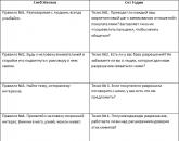
First of all, you need to decide who will conduct the research. Teamwork is one of the key principles of FMEA. Only this format ensures the quality and objectivity of the examination, and also creates space for non-standard ideas. As a rule, a team consists of 5-9 people. It includes:
- Project Manager;
- process engineer performing the development of a technological process;
- design engineer;
- a production representative or;
- customer service employee.
If necessary, qualified specialists from outside organizations can be involved in the analysis of structures and processes. Discussion possible problems and ways to solve them takes place in a series of meetings lasting up to 1.5 hours. They can be conducted both in full and in part (if the presence of certain experts is not needed to resolve current issues).

Study the project
To conduct an FMEA analysis, you need to clearly identify the object of study and its boundaries. If we are talking about a technological process, it is necessary to designate the initial and final events. For equipment and structures, everything is simpler - you can consider them as complex systems or focus on specific mechanisms and elements. Inconsistencies can be considered taking into account the needs of the consumer, the stage of the product's life cycle, geography of use, etc.
At this stage, the members of the expert group should receive detailed description object, its functions and principles of work. Explanations should be accessible and understandable to all team members. Usually, presentations are held at the first session, experts study instructions for the manufacture and operation of structures, planning parameters, regulatory documents, blueprints.
# 3: List Potential Defects
After the theoretical part, the team proceeds to assess possible failures. Compiled complete list all possible inconsistencies and defects that may arise at the facility. They can be associated with the breakdown of individual elements or their incorrect functioning (insufficient power, inaccuracy, low productivity). When analyzing processes, it is necessary to list specific technological operations, during the execution of which there is a risk of errors - for example, non-execution or incorrect execution.

Description of causes and consequences
The next step is an in-depth analysis of such situations. The main task is to understand what can lead to the occurrence of certain errors, as well as how the detected defects can affect employees, consumers and the company as a whole.
To determine the likely causes of defects, the team examines the descriptions of the operations, the approved requirements for their implementation, and statistical reports. In the FMEA analysis protocol, you can also specify the risk factors that the enterprise can adjust.
At the same time, the team thinks about what can be done to eliminate the chance of defects, proposes control methods and the optimal frequency of inspections.
Expert assessments
- S - Severity / Significance. Determines how severe the consequences of this defect will be for the consumer. It is evaluated on a 10-point scale (1 - practically do not affect, 10 - catastrophic, in which the manufacturer or supplier may be subject to criminal punishment).
- O - Occurrence / Probability. Shows how often a certain violation occurs and whether the situation can repeat itself (1 - extremely unlikely, 10 - failure is observed in more than 10% of cases).
- D - Detection. A parameter for evaluating control methods: will they help to timely identify nonconformity (1 - it is almost guaranteed to be detected, 10 - a hidden defect that cannot be detected before the onset of the consequences).
On the basis of these assessments, the priority number of risks (PRN) is determined for each type of failure. This is a generalized indicator that allows you to find out which breakdowns and violations pose the greatest threat to the company and its customers. Calculated by the formula:
| PChR = S × O × D |
The higher the HRF, the more dangerous the violation and the more destructive its consequences. First of all, it is necessary to eliminate or reduce the risk of defects and malfunctions in which given value exceeds 100-125. Violations with an average level of threat score from 40 to 100 points, and a HRP of less than 40 indicates that the failure is insignificant, occurs rarely and can be detected without problems.

After assessing the deviations and their consequences, working group FMEA identifies priority areas of work. The first priority is to establish a corrective action plan for the bottlenecks - the elements and operations with the highest HFR rates. To reduce the threat level, you need to influence one or several parameters:
- eliminate the original cause of the failure by changing design or process (score O);
- prevent the appearance of a defect using statistical control methods (score O);
- soften Negative consequences for buyers and customers - for example, to reduce the prices of defective products (score S);
- introduce new tools for early detection of faults and subsequent repair (grade D).
So that the enterprise can immediately start implementing the recommendations, the FMEA team simultaneously develops a plan for their implementation, indicating the sequence and timing of each type of work. The same document contains information about the executors and those responsible for carrying out corrective measures, sources of funding.

Summarizing
The final stage is preparation of a report for company executives. What sections should it contain?
- Review and detailed notes on the progress of the study.
- Potential causes of defects in the production / operation of equipment and the performance of technological operations.
- A list of the likely consequences for employees and consumers - separately for each violation.
- Assessment of the level of risk (how dangerous are possible violations, which of them can lead to serious consequences).
- A list of recommendations for maintenance, planners and planners.
- Schedule and reports on the implementation of corrective actions based on the results of the analysis.
- List potential threats and the consequences that were eliminated by changing the project.
All tables, graphs and diagrams are attached to the report, which serve to visualize information about the main problems. Also, the working group should provide the used schemes for assessing discrepancies in terms of significance, frequency and probability of detection with a detailed decoding of the scale (which means this or that number of points).

How to complete the FMEA protocol?
During the study, all data should be recorded in a special document. This is the "Protocol for the Analysis of Causes and implications of FMEA". It is a universal table where all information about possible defects is entered. This form is suitable for the study of any systems, objects and processes in any industry.
The first part is completed on the basis of personal observations of team members, study of company statistics, work instructions and other documentation. The main task is to understand what may interfere with the operation of the mechanism or the performance of a task. At the meetings, the working group must assess the consequences of these violations, answer how dangerous they are for workers and consumers and what is the likelihood that a defect will be discovered at the production stage.
The second part of the protocol describes options for preventing and eliminating inconsistencies, a list of measures developed by the FMEA team. A separate column is provided for the appointment of those responsible for the implementation of certain tasks, and after making adjustments to the design or organization of the business process, the manager indicates in the protocol a list of work performed. The final stage is re-scoring, taking into account all changes. By comparing the initial and final indicators, we can conclude about the effectiveness of the chosen strategy.
A separate protocol is created for each object. At the very top is the title of the document - "Analysis of the types and consequences of potential defects". The model of the equipment or the name of the process, the dates of the previous and next (according to the schedule) inspections, the current date, as well as the signatures of all members of the working group and its leader are indicated below.

An example of FMEA analysis ("Tulinovskiy instrument-making plant")
Let's consider how the process of assessing potential risks takes place on the experience of a large Russian industrial company. At one time, the management of the "Tulinovskiy Instrument-Making Plant" (JSC "TVES") faced the problem of calibrating electronic scales. The enterprise produced a large percentage of incorrectly working equipment, which the department technical control was forced to send back.
After examining the sequence of steps and requirements for the calibration procedure, the FMEA team identified four sub-processes that most affected the quality and accuracy of the calibration.
- moving and installing the device on the table;
- checking the position on the level (the scales must be placed 100% horizontally);
- placement of loads into platforms;
- registration of frequency signals.
What types of failures and malfunctions were recorded during these operations? The working group identified the main risks, analyzed their causes and possible consequences. On the basis of expert assessments, the HRP indicators were calculated, which made it possible to determine the main problems - the lack of clear control over the performance of work and the condition of the equipment (stand, weights).
| Stage | Failure scenario | Causes | Consequences | S | O | D | PChR |
|---|---|---|---|---|---|---|---|
| Moving and installing scales on the stand. | Risk of the balance falling due to the heavy weight of the structure. | There is no specialized transport. | Damage or breakdown of the device. | 8 | 2 | 1 | 16 |
| Checking the horizontal position on the level (the device must be absolutely level). | Incorrect graduation. | The table top of the stand was not leveled. | 6 | 3 | 1 | 18 | |
| Employees do not follow work instructions. | 6 | 4 | 3 | 72 | |||
| Arrangement of weights at the platform reference points. | Using weights of the wrong size. | Operation of old, worn out weights. | Quality Control Department returns the marriage due to metrological inconsistency. | 9 | 2 | 3 | 54 |
| Lack of control over the placement process. | 6 | 7 | 7 | 252 | |||
| The stand mechanism or sensors are out of order. | The combs of the movable frame are skewed. | Weights wear out quickly from constant friction. | 6 | 2 | 8 | 96 | |
| The cable broke. | Suspension of production. | 10 | 1 | 1 | 10 | ||
| The geared motor is out of order. | 2 | 1 | 1 | 2 | |||
| Schedule of scheduled inspections and repairs is not being followed. | 6 | 1 | 2 | 12 | |||
| Registration of frequency signals of the sensor. Programming. | Loss of data that was entered into the storage device. | Power outages. | It is necessary to re-calibrate. | 4 | 2 | 3 | 24 |
To eliminate risk factors, recommendations were developed for additional training of employees, modification of the stand tabletop and purchase of a special roller container for transporting scales. The purchase of an uninterruptible power supply unit solved the data loss problem. And to prevent future calibration problems, the working group proposed new schedules for maintenance and routine calibration of weights - checks began to be carried out more often, due to which damage and malfunctions can be detected much earlier.


Popular
- Quantum model of personality evolution
- Sell sales to everyone
- Selling secrets for all occasions
- Deming William Edwards New Economy Edward Deming New Economy
- How to register a company abroad?
- How the passenger pays for the trip Benefits of travel for corporate orders
- Organization of a paid extended day group as an idea for a private business!
- Own business: using thermal imaging cameras to inspect houses Thermal imaging cameras as a business can you make money
- Technology and timing of installation work
- Serbia - the life of Russian emigrants in the Balkans Cost and terms of company registration in Serbia