Shaft journal turning. What is a pump end seal for? Shaft straightening in a lathe
During operation, the shafts wear out the landing necks, keyways and splines, the threads and center holes are damaged, the shaft gets bent.
The method of repairing a worn cylindrical shaft is chosen after the nature and degree of wear has been established by an appropriate check. Shaft journals with wear (scratches and risks, non-cylindricalness up to 0.1 mm) are repaired by grinding. But first, they check whether the center holes of the shaft are serviceable, in the presence of nicks and dents, first of all, they restore the center holes by turning. Then the shafts rule.
Shaft journals with significant wear are turned and ground to the repair size. In this case, it is allowed to reduce the diameter of the necks by 5-10%, depending on the nature of the loads perceived by the shaft, in particular, on whether the shaft experiences shock loads. In those cases where it is necessary to restore the original dimensions of the necks, repair bushings are pressed onto the necks after they have been turned or installed on 31xide glue, which are then machined by turning or grinding. Worn surfaces of shafts can also be repaired by building up metal by vibro-arc surfacing, metallization, hardening, chromium plating and other methods.
Bent shafts straighten cold or hot. Rolls with a diameter greater than 60 mm are subjected to hot straightening.
Cold straightening of the shafts can be done manually using screw clamps, levers, but it is better to do the straightening under a press.
The essence of editing lies in the fact that the applied force causes residual deformations, the part is restored, acquiring its original properties.
When cold dressing with a press or a bracket, the shaft is placed on two supports with the curved side to the loading device (screw, slider) and loaded so that the shaft bends in the opposite direction by an amount almost equal to the original deflection, and only then restore the original straightness accuracy.
Curved shafts up to 30 mm in diameter can be hardened. The essence of such editing is that the shaft is placed with a deflection down on the plate (Fig. 61) and frequent blows are applied with a light hammer until the shaft straightens. Impacts are also applied on both sides of the deflection, limited by an angle of 120 °.

Particularly high requirements are imposed on the spindles, therefore, the landing necks 1 and 2 (Fig. 62, a) of the spindles are processed by grinding. Their coaxiality must be maintained with an accuracy of 0.01 mm, the permissible non-roundness of the necks is 0.01 mm, non-cylindricality is 0.003-0.005 mm. Surface 3 must meet the same requirements. Conical holes 4 and 5 of the spindle must be concentric with the necks; beating is allowed 0.01-0.02 mm per 300 mm length.

First of all, the spindle wears out the bearing journals, seats for gears and other rotating parts. Scratches and scuffs appear on them, easily detected by external inspection.
It is advisable to repair the spindles several times, since the manufacture of a new spindle is complex and expensive. However, in cases where the repair of the spindle entails the repair of the parts mating with it, it may be more profitable to replace
worn spindle with a new one. This issue is solved by comparing the cost of repair work and a new spindle.
Spindles, in which the wear of the necks in diameter is 0.01-0.02 mm, are repaired by lapping on a lathe, performed with a special tool - a press (Fig. 63). Zhimok consists of a ring-clamp 1, a bolt 2, a lapping sleeve 3 with a cut and a handle-holder, which is not shown in the figure. The lapping sleeve is made of cast iron, copper or bronze, and the hole in it is made according to the size of the neck being processed.

Starting to grind the neck, apply a thin layer of a mixture of fine emery powder and oil on it, after which they put on a squeeze and slightly tighten the bolt 2. Start the machine by setting it to a spindle speed of 10-20 m / min. When the spindle rotates, the press is evenly driven along the processed neck. From time to time, a layer of powder with oil is renewed and bolt 2 is tightened.
Having eliminated wear, the spindle neck is washed and lapped with kerosene, then a thin layer of kerosene polishing paste is applied to the neck and its processing is completed.
When the wear of the spindle necks is more than 0.02 mm, they are repaired by grinding, followed by lapping to the repair size. However, this method of repair is acceptable only when it is possible to resize the holes in the bearings or other parts mating with the spindle accordingly. If this is not possible or changing the size of the holes is impractical due to the high complexity of the operations, the spindle necks are restored with wear up to 0.05 mm with chromium build-up, and with wear more than 0.05 mm - with vibro-arc surfacing.
Spindle necks with a chromium layer grown on them are processed by grinding, but if other metals are applied to the necks in correspondingly larger layers than with chromium plating, the necks are first turned and therefore polished. At the same time, they are given a taper of up to 0.01 mm towards the rear end, so that when scraping the bearings, the paint layer applied to the journals is completely used to paint the surface of the bearings.
Worn spindle journals, on which rolling bearings or other parts with a fixed fit are mounted, are very convenient to restore electrolytically.
Spindle necks (for plain bearings, including those with axial microcracks) are restored by installing thin-walled compensation fittings or inserts on the glue. Practice shows that such spindles serve for a long time, and in some cases work better than new ones, if the fittings ("shirts") and inserts (bushings) are made of materials with better performance properties. At the same time, significant savings in materials are achieved and repair costs are reduced.
To install compensation fittings or inserts, a layer of metal is ground off the surface of the spindle in order to fit the corresponding part of the compensator in the form of a sleeve with a nominal size or an increased repair size of the restored surface. In this case, the removed metal layer should be minimal, up to 10-15% of the nominal diameter of the solid section of the shaft or the wall thickness of the hollow spindle.
To restore a fixed fit, for example, the surface of a spindle for a rolling bearing, the compensation lining (sleeve) can be thin-walled - from 0.5 to 2 mm, and when restoring the spindle neck for a plain bearing, the wall thickness of the lining must be at least 2.5 mm.
Compensatory thin-walled fittings are made of metal corresponding to the material of the repaired shaft or from a material that meets increased requirements.
The inner diameter is made in place with a gap of 0.05 mm in diameter (surface roughness Rz 20), the outer diameter is made with an allowance of 3-5 mm. The final processing is carried out with intensive cooling after the installation of the sleeve and the curing of the adhesive after 24 hours.
Expansion bushings with a thickness of 2.5-3.5 mm and more appropriate to be made of case-hardened steel. The recoverable diameter is made with an allowance of 0.3 mm, and the diameter of the sleeve mating with the shaft, spindle or axle is machined with an allowance of 3-4 mm. After carburizing, the carburized metal layer is removed from this surface and the bushing is hardened to HRC58-60.
The non-hardened surface of the sleeve is machined on a lathe according to the size of the prepared shaft surface with a gap of 0.05 mm in diameter (surface roughness). The hardened repairable surface of the sleeve is finally ground after it has been installed on the shaft and the adhesive has cured.
On fig. 62 shows schemes for repairing machine spindles by installing compensation fittings and inserts on epoxy glue. At the lathe spindle, the rear neck 1 (see Fig. 62, a) was restored for the rolling bearing, the hardened support surface 2 for the plain bearing and the conical surface 3 for the chuck. The conical surface 9 (see Fig. 62, b) for the roller bearing (series 3182100) and the guide 10 for the cartridge were also restored. The taper hole of the spindle is restored with an insert 11 with a hardened hole.
Necks (see Fig. 62, b) of the spindle drilling machine restored with thin-walled (less than 1 mm) extensions 6 and 8, while the extension 6 is made of two half-bushings, along the edges of which two pins 7 are placed on glue. film, so the operation is performed with abundant cooling.
Before turning and grinding, the following preparatory work is carried out. Steel plugs are turned and firmly inserted into holes 4 and 5 of the spindle, having previously cleaned the plugs' landing sites. After that, the spindle is fixed with one end in the lathe chuck, and the second end is installed with a non-worn place in the steady rest and the spindle is calibrated for runout, which should not exceed 0.005 mm; then make a center hole in the cork. After that, the spindle is rearranged, its second end is clamped in the chuck, and the first end is in the steady rest, and a second center hole is made. Now the spindle is installed in the centers and the correct centering is checked; the runout of unworn places on the indicator should be no higher than 0.01 mm.
After completing the described operations, proceed to the processing of the spindle by turning and grinding.
In case of damage and wear of the spindle thread during restoration, surfacing is used, followed by threading to the nominal size. Recutting the thread to a smaller diameter is not recommended, as it becomes non-standard.
The worn taper hole of the spindles is repaired in different ways depending on the amount of wear. In case of severe wear, the hole is bored and then a bushing is glued or pressed into it. With little wear, the hole (shallow risks, slight nicks) is ground, removing the minimum layer of metal.
Machining of the taper hole of the spindle can be performed without removing the spindle from the machine, which ensures good centering of the hole axis with the spindle axis. When processing a taper hole in place, fixtures are used.
The accuracy of the taper bore of the spindle is checked with a standard taper gauge. The control mark on the gauge should not enter the hole, there should be a distance of 1-2 mm between it and the end of the spindle. If the control risk of the caliber enters the conical hole and is hidden, then trimming the front end of the spindle by 2-3 mm is allowed.
The axis of the tapered hole of the spindle is checked for runout with an indicator on the control mandrel inserted into the hole. A deviation from the axis of 0.01 mm at the end of the spindle and 0.02 mm at a length of 300 mm is allowed. Surface 4 of the spindle can have a runout limit of 0.01 mm.
Above it was said about spindles with chrome-plated necks. It has been established that such spindles work well only if the bearing fits perfectly to them, when a gap is provided for lubricating the journals. The normal value of this gap is 0.006-0.02 mm, depending on the accuracy of the machine, the highest speed and spindle diameter. With careless fitting during operation of the machine, increased local heating occurs. Because of this, small cracks form on the chrome-plated surface, the chrome peels off, the spindle neck and the bearing surface are damaged.
The storage of repaired or new shafts and spindles must be free from bending and deformation. A carelessly placed shaft can bend under its own gravity. To prevent this, it is recommended to place the shafts in special racks in a vertical state. The best storage method is hanging upright.
Shafts and axles have the following main defects: wear of the landing journals, malfunction of keyways and splines, deterioration of the thread, twisting of the shafts, the appearance of cracks and breaks.
The restoration of these elements occurs according to the following principle: parts are washed, then they are cleaned and defective. The bent condition is corrected by editing a cold or hot type, and some models are disposed of as a marriage. If the deflection is small, then you can grind and machine the shaft or axle.
Specialists of the HydroSpetsTech company can carry out repair work qualitatively and quickly. Real professionals work here.
Shaft dressing by bending
Shafts that are suitable for dressing are placed in the mounting prism so that the concave place looks up. Next, the shaft is bent by a pressure device.
If the shaft is thin or long, then it is used for dressing lathe. Bending occurs due to the emphasis of the machine.
Hardening is used to correct the shape of the shaft. To do this, the product is placed on a calibration plate so that the deflection is from below. Then strikes of small force are applied. This is done with a bang.
During dressing, cracks often form, so they need to be checked with a flaw detector. If defects are found, then heat treatment should be carried out. Next, you should grind and grind the products.
Shaft and axle repair by heating and cooling
If the shaft is deformed, then it is possible to correct it due to heating. To do this, heat treatment with a gas flame is used in the place where there is a curvature. The indicator allows you to calculate the degree of deformation. Asbestos is used for piercing and compressed air cooling.
Repairs to journals on trunnions can be repaired by reconditioning or machining. To do this, the metal is subjected to surfacing and sizing. Thus, it is possible to increase the volume by reducing the length or vice versa.
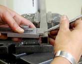
Small scuffs, cracks and risks can be easily eliminated by finishing with GOI paste or oils with emery powder. All this is done after fixing the element on the machine, where rotational movements are carried out.
Prices for any complexity can be obtained from the managers of the Hydrospetstech company.
During upsetting, the area of the shaft seat can be heated up to 900C. Next, the product is subjected to cooling in the aquatic environment. After that, the blows are applied, as a result, the shaft becomes wider. A hole is drilled in the end of the shaft, which is suitable for the length of the seat.
To repair the shaft, compensator bushings can be used. In this version, the trunnion is machined to a smaller size, a steel sleeve is pressed into it, the ends of which are welded to the end of the trunnion. All products are fixed together and the outer surface is processed. Sizes can be customized to suit any requirement.
Keyway repair
 Keyways can be repaired to nominal and oversize. In the first variant, the product is melted and cut. In the second option, expansion to the desired size and filing or milling and planing takes place.
If the key grooves are large, then one-sided surfacing is carried out, then mechanical type processing to the desired size.
The splined part of the shaft or axle is restored under the influence of a blunt chisel or a sharp roller. Next comes the machining. All this is done with minor damage.
If the product has suffered a lot of wear, then the slots are melted in parts or on the sides. Next, cut to the required size and grind. In some cases, damaged parts are cut off and new elements are welded on.
In case of damage to the thread, you can use the machine tool or surfacing with cutting the desired length. Electroslag welding, ring arc welding can also be used for repairs. For dumbbells, filing and turning of the product is used. Clamping rings are used for keyed connections.
Repair work can be ordered by contacting the specialists of HydroSpetsTech. The site is at the link.
Damage to the bearings of electric motors in the most severe cases is accompanied by a curvature of the rotor shaft. Shaft distortion is caused by the fact that when a bearing fails due to subsidence or strong vibration of the rotor, the rotating shaft touches the bearing seal. At the first moment, the shaft touches the seal on one side. This leads to one-sided heating of the shaft, which causes expansion of the outer layers of the metal at the place of heating and bending of the shaft, with its convexity turned towards the contact. The appearance of a bend, in turn, increases the friction and local heating of the shaft. The vibration of the rotor is intensified. The curvature of the shaft increases. If the electric motor is not turned off by the personnel, then the rotor barrel will inevitably touch the stator, ending in damage to the iron and the stator winding and disconnecting the electric motor from protection.
If the rubbing was not strong AND not long, then after cooling the shaft may straighten out, or the residual curvature will be insignificant. For strong grazing, the residual curvature will be large.
In some cases, shaft distortion occurs as a result of the heating of the shaft due to the rotation of the inner ring of the rolling bearing on it.
To determine the magnitude of the curvature of the shaft, the rotor is mounted on a lathe so that the boom of the necks at the ends of the shaft does not exceed 0.02-0.03 mm according to the indicator. Then, the shaft break is checked with an indicator near the place of its heating and in places of a stepwise change in its diameter. The battle of the rotor barrel near both ends is also checked. When measuring, the points of the circle on the shaft are determined and marked, giving the greatest deviation of the indicator needle. The largest deviation of the indicator pointer clockwise corresponds to the maximum convexity of the shaft, and the largest deviation counterclockwise corresponds to the maximum hollow of the shaft in this section.
For rotors with a rotation speed of 3,000 rpm, a shaft curvature of up to 0.03 mm is permissible, i.e., shaft breakage according to the indicator is permissible up to 0.06 mm. For rotors with a rotation speed of 1,500 rpm and below, the shaft break according to the indicator is permissible up to 0.10 mm.
With small shaft distortions (up to 0.12 mm in electric motors with a rotation speed of 3,000 rpm), in some cases, instead of straightening, it is possible to limit oneself to balancing the rotor. With shaft distortions greater than 0.12 mm, the clearances in the bearing seals may be insufficient, and it is not recommended to increase them. Balancing can be hampered by the inability to place sufficient weight on the rotor. The battle of the rotor barrel - and this is perhaps the most significant - can lead to unacceptable asymmetry in the air gap between the rotor and the stator. Sometimes the battle of the rotor barrel is eliminated by turning it. But at the same time, the diameter of the rotor barrel decreases, the air gap between the rotor and the stator increases, the no-load current increases and the starting torque decreases. Therefore, one should not resort to the groove of the rotor barrel.
The shaft can be straightened by local heating, mechanically or thermomechanically. With local heating, the shaft is straightened by heating it from the convex side.
Due to the relatively small diameter of the shafts of electric motors, it is not always possible to straighten them with the help of local heating without the use of mechanical pressure with significant curvature. For mechanical pressure, it is required to make a frame with goats and a pressure device, which complicates the editing.
Therefore, it is most expedient to straighten the shafts of electric motors mechanically.
Shaft straightening mechanically. The rotor in this case is installed so that the concave side of the shaft is facing up. A beam or other rigid support is placed under the shaft in the place of its maximum deflection.
The shaft is corrected by riveting it with the help of chasing in the place of maximum bending, from the concave side. During riveting, the outer layers of the metal expand and cause the shaft to bend in the direction opposite to the original bend, i.e. straighten it.
During hardening, the surface of the shaft loses its cylindrical shape and gets dents. It is unacceptable to correct the surface with a groove, since the work-hardened layers will be removed and the shaft will return to its previous position. Therefore, hardening cannot be done on the working journals of the shaft and at the locations of the bearing seals. To do this, the non-working sections of the shaft closest to the place of maximum curvature are selected, preferably at the transition points of one section of the shaft to another.
Chasing is made from a chisel by grinding off its sharp end, as shown in Fig. 36. The edges of the working end of the coinage are rounded off.
Hardening starts from the top point of the shaft and gradually move the blows down the circumference from one side or the other from the top point. The hardening should occupy one third of the circumference. If hardening along one circle does not completely straighten the shaft, then, having retreated along the axis of the shaft by 10-15 mm, cold hardening is performed along a new circle.
You should periodically check the results of editing with the indicator. It is advisable to work straightening by hardening after obtaining a small, but acceptable by the standards, bending of the shaft from a straight line in the direction opposite to the initial bend.
Shaft straightening by thermomechanical method. In contrast to dressing by local heating, with this method the shaft is heated over the entire circumference and over the entire cross section up to 600-650 ° C and, when heated, bends in the direction opposite to the curvature using a pressure device.
Due to some complexity and the need to make a calculation to determine the forces of pressing on the shaft, at which the maximum allowable stresses in it would not be exceeded, this method, as a rule, is not used for straightening the shafts of electric motors at the place of their installation.
1. Uneven cooling of the fixed shaft after the turbine stops. The lower part of the shaft is cooled more than the part above. Due to uneven cooling, the fibers at the bottom of the shaft contract more than the fibers at the top.
2. Uneven cooling of the turbine cylinder. Reason: poor quality of thermal insulation, or the presence of stagnant zones in the protective casing of the turbine.
3. Touching the labyrinth, annular or diametrical
4. Wrong landing of a disk on a shaft.
5. Insufficient axial clearances between turbine rotor parts.
6. Large mechanical stresses. May occur during hard braking.
In the presence of one of the above reasons for rotating, which leads to a decrease in radial clearances, touching of the rotor parts on the stationary parts of the turbine. With such rubbing, friction occurs, which leads to heating and deflection of the shaft in the direction of grazing.

a) shaft
cooling
a) shaft
As a result of grazing, this place of the shaft heats up and the metal fibers tend to expand, respectively, and the heating temperature, but this is prevented by the surrounding colder metal layers. In cold metal, residual deformations occur.
Shaft straightening.
It is produced if the deflection exceeds 0.06 mm.
Before editing, it is necessary to carry out preparatory operations:
Shaft inspection. The revealed place of the defect is cleaned and subjected to chemical treatment in order to detect cracks. When they are detected, cracks are removed on a lathe by removing chips. As long as the crack is not removed, the chips in the place where the crack is present will break off, the end of chip separation indicates the complete removal of the crack. This operation is coordinated with the manufacturer. After the removal of cracks, the shaft is subjected to repeated etching and after that they begin to work.
There are several types of shaft straightening:
1. Thermal straightening.
It consists in one-sided local heating of the outlet side of the shaft to a temperature above the yield point. The heated fibers tend to expand, but receive resistance from the non-heated areas, straighten due to elastic-plastic deformation, i.e., they perform the reverse operation in which the deflection occurred.
2.Mechanical straightening.
It is produced in a cold state by chasing in places of the greatest deflection. The essence of the method lies in embossing to stretch the fibers of the shaft compressed during operation.
3. Thermomechanical straightening.
Combined method.
The stress relaxation method is: the shaft section is heated to a temperature of 600-650 0 C and with its subsequent deflection in the direction opposite to the curvature. The shaft is heated from induction windings. The method is based on the phenomenon of creep and stress relaxation and is applied in several stages. This is an improved thermomechanical method.
Manufacture of repair of broken shafts.
The broken parts of the shaft are connected in two ways:

The most common way to restore deformed parts that do not have cracks and surface wear to unacceptable limits is forging. More often than others, machine parts are deformed (bent), having small dimensions in cross section and thickness and large in length and width. Such parts include shafts, axles, levers, rims, beams, frame channels, etc. They are edited in cold or in hot states. Cold straightening is used only for low-responsibility parts, since after straightening they eventually lose their original shape and bend again. To relieve internal stresses formed during cold straightening, critical parts, if their dimensions allow, are subjected to medium tempering (see Fig. 8.2), that is, heated to a temperature of 400 ° C, and then slowly cooled in air or in sand.
Parts and assembly units are corrected on anvils or straightening plates (see Fig. 7.12, e) forging hammers and with the help of special fixtures and stands.
Methods for cold dressing of shafts and axles are shown in fig. 12.1. Shafts or axles are placed in prisms with a bulge up and straightened using a manual fixture (Fig. 12.1, a) or a screw press (Fig. 12.1, b). Shafts or axles made of low-carbon and medium-carbon steels are straightened by double dressing. To do this, the shaft or axle is placed in prisms with the convex side up (Fig. 12.1, c) and bent them //i (Fig. 12.1, d) several times larger than the original
Rice. 12.1. Methods for straightening rods and shafts
deflection N. After removing the load, the deflection of the shaft in the opposite direction will be approximately equal to the initial deflection N. Then the shaft is rotated 180 ° (Fig. 12.1, e) and bend it until the deflection is eliminated (Fig. 12.1, e).
Shafts with a diameter of more than 30 mm, made of high-carbon steels, are first heated in places of deflection in a hearth or with a gas burner to a temperature of 750 ... .
Shafts made of pipes are covered with dry sand to prevent crushing before straightening, and wooden plugs are hammered into the end holes. Straightening should be carried out carefully to prevent the pipe seam from opening. Small local deformed places are eliminated in a cold state. If the seam opens, then it is welded with gas welding.
Twisted shafts in the middle part are heated to a temperature of 830...900°C (red heat). One end of the shaft is clamped in a vice, and the other is turned in the direction opposite to the direction of twisting (see Fig. 7.17). If the shaft is heat treated,

then after straightening with heating, the heated areas must be heat-treated again. |
Bent hardened shafts or medium carbon steel shafts are straightened by cold work hardening. ] To do this, the shaft is placed on the anvil with the bulge down (Fig. 12.2, a) and with the toe of a small hammer, frequent, but not strong blows are applied to the shaft, starting from the middle to its ends. The hammer must be with a wedge-shaped back (see Fig. 3.2, c) without nicks. As a result of the formation of a work-hardened layer, the shaft is straightened (Fig. 12.2, b). After such straightening, almost zero runout is obtained and heat treatment is not required in this case.
Braces, crossbars, scarves and other parts that are easily removed from the frames and other parts of the machine are corrected on an anvil or a straightening plate (see Fig. 7.12, e) in cold and hot states.
Small parts with a rectangular section can be straightened in the same way as shafts and axles, or using the simplest screw fixture shown in fig. 12.3, a.
curved large parts and assembly units from rolled products in the form of beams are usually straightened with the help of jacks and simple screw fixtures.
In fixture<рис. 12.3. б) выправляют балки рам 3 jack force 6. The jack is installed on the beam /, to which the clamps are attached 2, a bent frame beam is placed between the clamps on the jack 3, above it, fingers are inserted into the holes of the clamps 4 and install studs between the shelves 5 with nuts that protect the beam flanges from additional deformation.
The fixture shown in fig. 12.3, c, consists of a screw mechanism 7, a box 8, welded from two channels, and clamps 9. The place of deflection at the channel 10
heated to a temperature of 800 ° C (light cherry color of heat), using clamps, the device is installed on the channel and the channel with a screw mechanism
straighten out.
A device for straightening bent channel flanges is shown in fig. 12.4. It consists of a stand / clamping pad 4 and bolt^Z. Channel 2, heated to a temperature of 650 ... 750 ° C (cherry color of heat) at the place of deformation, mounted on a rack and pressed with a clamping plate and a bolt, and then the deformed place of the channel is straightened with sledgehammer blows.
Twisted channel 3 frames (fig. 12.5) can be straightened on the correct plate / with studs 2 with the aid of a bracket 6 and curved lever 4, upon which, in order to create great effort,
install pipe 5.
Such devices can be used to straighten channels and other rolled profiles without separating them from the frame or other parts of the machine.
The technology of straightening shaped parts can be shown on the example of straightening the metal rim of an agricultural wheel.

Rice. 12.3. Device for straightening products such as beams

Rice. 12.4. Editing a bent Fig. 12.5. Editing the twisted wall of the channel channel
economic machine. The cross sections of such wheels come in a wide variety of shapes: flat rectangular, low trough, round grooved, flat grooved, etc.
The deformed rim of the wheel is corrected in the forge. If the rim is very deformed and cannot be straightened in a cold state, then it must first be heated to a temperature of 800 ... 850 ° C in a furnace or with a gas burner. A rim with a flat rectangular section is ruled on an anvil with a trowel and a sledgehammer. A rim with a complex profile is ruled in a special device (Fig. 12.6), consisting of a plate /, a folding bracket 4, axes £ and interchangeable crimps 2 with a working surface made in the form of a rim. Heated deformed rim 5 set between crimps and sledgehammer blows 3 on the folding bracket, the rim is edited, turning it as necessary. Turning is carried out freely thanks to the folding bracket.
 |
Bent wheel spokes are straightened on a stand with hammer or sledgehammer blows. With a significant bending of the spokes, they are heated in a blacksmith's grinder or with a gas burner to a temperature of 750 ...
Rice. 12.6. Wheel rim straightener
Straightened parts from profiles and shaped parts after editing can be strengthened with scarves, stiffeners and overlays, otherwise they will deform again when force is applied.


Popular
- New Year in the work team (corporate)
- GIT check: what is checked and how to prepare
- Maintenance of military records in the organization
- Orthodox photographer - the best in Eurasia!
- We remember and are proud: original ideas for the script for Victory Day
- Is it worth calling the employer after the interview or how to find out the results: how long do they usually report?
- Features of the technique of painting plates, painting ceramic dishes White-blue painting on dishes
- Types of dish painting: Gzhel, Gorodets, Zhostovo, Khokhloma
- Marketer: job responsibilities Job description of an IT company marketer
- Child care center administrator job description