Supports of distillation columns GOST. How to make a distillation column - calculation of system parameters
1. Design assignment
2. Theoretical part
3. Scheme of distillation column
4. Calculation of the distillation column
4.1 Material balance. Working line equations
4.5 Thermal calculation of the installation
List of sources used
1. Design assignment
Calculate and design a rectification column (dish-shaped) for separating a mixture of acetic acid - water incoming in the amount of 10 tons per hour. The composition of the initial mixture of 10% (wt.) acetic acid and 90% (wt.) water. The required content of acetic acid in the distillate is 0.5% (wt.), and in the distillation residue 70% (wt.). Rectification is carried out under atmospheric pressure. The heating steam has a pressure P est =3 atm.
Technical specifications
1. The device is designed to separate a mixture of acetic acid - water with a concentration of 10% (mass).
2. Heating steam has pressure Р=3 atm.
3. The temperature of the medium in the cube is up to 105°C.
4. The environment in the apparatus is non-toxic.
5. Type of plates - sieve.
6. Number of plates - 33.
Technical requirements
1. During the manufacture, testing and delivery of the apparatus, the following requirements must be met:
A) GOST 12.2.003-74 "Production equipment. General requirements security"
B) GOST 26-291-79 "Steel welded vessels and apparatus. Technical requirements"
2. The material of the plates or parts of the column in contact with the separated liquids or their vapors is made of steel Kh18NYUT GOST 5949-75, the remaining elements of the column are made of steel Vst Zsp. GOST 380-71.
3. Test the apparatus for strength and density hydraulically:
A) in a horizontal position - pressure 0.2 MPa;
B) in a vertical position - in bulk.
4. Welded joints must comply with the requirements of OH 26-01-71-68 "Welding in chemical engineering." Welding in St. Zsp. Produce with an electrode brand ANO-5-4.5-2 in accordance with GOST 9467-75.
5. Welds in the volume of 100% control by X-ray transmission.
6. Paronite gaskets PON-1 GOST 481-71.
7. Unspecified nozzle extension 150mm.
8. Dimensions for reference.
2. Theoretical part
Rectification is a process of repeated partial evaporation of the vapor condensation liquid. The process is carried out by contacting vapor and liquid flows having different temperatures, and is usually carried out in column apparatus. At each contact with the liquid, the predominantly low-boiling component evaporates, with which the vapors are enriched from the vapors, the predominantly high-boiling component is condensed, passing into liquids. Such a two-way exchange of components, repeated many times, makes it possible, in the end, to obtain vapors that are almost a pure low-boiling component. These vapors, after condensation in a separate apparatus, give a distillate (rectified) and phlegm - a liquid returned to irrigate the column and interact with the rising bunks. Steam is obtained by partial evaporation from the bottom of the column of the residue, which is almost pure high-boiling component.
Rectification has been known since the beginning of the 19th century as one of the most important technological processes, mainly in the alcohol and oil industries. Currently, rectification is increasingly used in various areas of chemical technology, where the isolation of components in a pure form is very important (in the production of organic synthesis, isotopes, polymers, semiconductors, and various other high-purity substances).
The rectification process is carried out by repeated contact between non-equilibrium liquid and vapor phases moving relative to each other.
When the phases interact between them, mass and heat transfer occurs due to the tendency of the system to a state of equilibrium. As a result of each contact, the components are redistributed between the phases: the vapor is somewhat enriched with a low-boiling component, and the liquid is enriched with a high-boiling one. Multiple contacting leads to almost complete separation of the initial mixture.
The device of rectifiers.
Rice. 1 Distillation column of continuous action.
1 - column; 2 - boiler; 3 - dephlegmator
Thus, the absence of equilibrium (and, accordingly, the presence of a phase temperature difference when the phases move at a certain relative speed and are repeatedly contacted) are necessary conditions for rectification.
Rectification processes are carried out periodically or continuously at various pressures: at atmospheric pressure, under vacuum (for separating mixtures of high-boiling substances), as well as under pressure greater than atmospheric pressure (for separating mixtures that are gaseous at normal temperatures).
To carry out rectification processes, apparatuses of various designs are used, the main types of which do not differ from the corresponding types of absorbers.
In distillation plants, two types of apparatus are mainly used:
packed and tray distillation columns. In addition, for rectification.
vacuum used film and rotary columns of various designs
Packed, bubbling, and also some film columns are similar in design of internal devices (trays, packed bodies, etc.) to absorption columns. However, unlike absorbers, distillation columns are equipped with heat exchange devices - a boiler (cube) and a dephlegmator (Fig. 1). In addition, to reduce heat loss to the environment, distillation apparatuses are covered with thermal insulation.

Fig- 2. Installation options for dephlegmators
a - on the column: b - below the top of the column;
1 - reflux condensers; 2 - columns: 3 - pump.
Boiler or cube, designed to vaporize part of the liquid flowing from the column, and supply steam to its lower part (under the nozzles or bottom plate). Boilers have a heating surface in the form of a coil or are a shell-and-tube heat exchanger built into the bottom of the column. More convenient for repair and replacement are remote boilers that are installed below the column in order to ensure natural circulation of the liquid.
The reflux condenser, designed to condense vapors and supply irrigation (reflux) to the column, is a shell-and-tube heat exchanger, in the annular space of which vapors usually condense, and a cooling agent (water) moves in the pipes.

Rice. 3. Mesh column.
a - diagram of the device of the column; b - diagram of the plate device; 1 - body; 2 - plate; 3 - overflow pipe; 4 - glass.
In the case of partial condensation of the reflux condenser, it is placed directly above the column to ensure greater compactness of the installation, or outside the column (Fig. 2). In this case, condensate (phlegm) from the lower part of the dephlegmator is fed directly through a hydraulic seal to the top of the column, since in this case there is no need for a reflux divider.
In the case of complete condensation of vapors in the dephlegmator, it is installed above the column, directly on the column or below the top of the column in order to reduce the overall installation height. In the latter case, the phlegm from the reflux condenser 1 is fed into the column 2 by a pump. This placement of the reflux condenser is often used when installing distillation columns outside buildings, which is more economical in temperate climates.
Bubbling (dish) columns.(Figure 3). These devices are the most widely used in rectification processes. They are applicable for large capacities, a wide range of changes in steam and liquid loads, and can provide a very clear separation of mixtures. During rectification, an increase in hydraulic resistance leads only to a slight increase in pressure and, accordingly, an increase in the boiling point of the liquid in the column boiler. However, the same disadvantage remains valid for vacuum distillation processes.
Sieve plates. (Fig. 3). A column with sieve plates is a vertical cylindrical body with horizontal plates, in which a significant number of holes with a diameter of 1-5 mm are drilled evenly over the entire surface. The gas passes through the holes of the plate and is distributed in the liquid in the form of small streams and bubbles. Sieve plates are characterized by simplicity of device, ease of installation, inspection and repair. The hydraulic resistance of these plates is small. Sieve trays operate stably in a fairly wide range of gas velocities, and in certain gas and liquid loads, these trays are highly efficient. However, sieve trays are sensitive to contaminants and sediments that clog the openings of the trays.
capped plates.
They are less sensitive to contaminants than sieve ones and are characterized by a higher interval of stable operation of the column with capped trays. The gas enters the plate through the branch pipes, then breaking up through the slots of the cap into a large number of individual jets. Next, the gas passes through a layer of liquid flowing over the plates from one downcomer to another.

Rice. 4. Scheme of operation of the cap plate
When moving through the layer, a significant part of the small jets break up and the gas is distributed in the liquid in the form of bubbles. The intensity of foam formation directly on the column or below the top of the column in order to reduce the overall height of the installation. In the latter case, the phlegm from the reflux condenser 1 is fed into the column 2 by a pump. This placement of the reflux condenser is often used when installing distillation columns outside buildings, which is more economical in temperate climates.
Bubbling (dish) columns. (Figure 3). These devices are the most widely used in rectification processes. They are applicable to large capacities, a wide range of steam and liquid loads and can provide very clear separation of mixtures. The disadvantage of bubbling apparatus is a relatively high hydraulic resistance - in conditions of distillation it is not significant. During rectification, an increase in hydraulic resistance leads only to a slight increase in the boiling point of the liquid in the column boiler. However, the same disadvantage remains valid for vacuum distillation processes.
In such columns, various types of plates are used: sieve, cap, failure, valve, plate, etc.
Sieve plates. (Fig. 3). A column with sieve plates is a vertical cylindrical body with horizontal plates, in which a significant number of holes with a diameter of 1-5 mm are drilled evenly over the entire surface. The gas passes through the holes of the tray and is distributed in the liquid in the form of small streams and bubbles. Sieve trays are simple in design, easy to install, inspect and repair. The hydraulic resistance of these plates is small. Sieve trays operate stably in a fairly wide range of gas velocities, and in certain gas and liquid loads, these trays are highly efficient. However, sieve trays are sensitive to contaminants and sediments that clog the openings of the trays.
Cap plates. They are less sensitive to contaminants than sieve ones and are characterized by a higher interval of stable operation of the column with capped trays. The gas enters the plate through the branch pipes, then breaking up through the slots of the cap into a large number of individual jets. Next, the gas passes through a layer of liquid flowing over the plate from one downcomer to another. When moving through the layer, a significant part of the small jets break up and the gas is distributed in the liquid in the form of bubbles. The intensity of the formation of foam and splashes on capped plates depends on the speed of gas movement and the depth of immersion of the cap into the liquid. Cap plates are made with radial or diametrical liquid overflows. Capped trays work stably under significant changes in gas and liquid loads. Their disadvantages include the complexity of the device and the high cost, the limiting load of it on gas is low, the hydraulic resistance is relatively high, and the difficulty of cleaning.
Valve plates. (Fig. 5). The principle of operation of valve discs is that a freely lying or freely lying round valve above the hole in the plate with a change in gas flow rate automatically adjusts with its weight the size of the gap area between the valve and the plane of the plate for the passage of gas and thereby maintains a constant gas velocity when it flows out in bubbling layer.
Ras. 5. Valve plates.
a, b - with round caps; c, with plate valve; g - ballast; 1 - valve; 2 - bracket-limiter; 3 - ballast.
At the same time, with an increase in the gas velocity in the column, the hydraulic resistance of the valve disc increases slightly. The valve lift is limited by the height of the restrictor bracket and usually does not exceed 8 mm.
Advantages of valve discs: relatively high gas throughput and hydrodynamic stability, constant high efficiency over a wide range of gas loads.
Packed columns. These columns use various types of packing, but Raschig ring packed columns are the most common in the industry. The lower hydraulic resistance of packed columns compared to bubbling columns is especially important for distillation under vacuum. Even with a significant vacuum in the upper part of the column, due to high hydraulic resistance, its rarefaction in the boiler may not be sufficient for the required reduction in the boiling point of the initial mixture.
To reduce the hydraulic resistance of vacuum columns, I use nozzles with the largest free volume possible.
No heat needs to be removed in the distillation column itself. Therefore, the difficulty of removing heat from packed columns is rather an advantage than a disadvantage of packed columns under the conditions of the distillation process.
Film machines. These devices are used for rectification under vacuum of mixtures with low thermal stability when heated (for example, various monomers, polymers, as well as other products of organic synthesis).
Film-type distillation apparatus achieves low hydraulic resistance. In addition, fluid retention per unit volume of the operating apparatus is small. Film distillation apparatuses include columns with regular packing in the form of stacks of vertical tubes with a diameter of 6–20 mm (multi-tubular columns), as well as stacks of plane-parallel or honeycomb packing with channels of various shapes, fabricated and perforated metal sheets or metal mesh.
Disadvantages of rotor columns: limited height and diameter (due to the complexity of manufacturing and the requirements for the strength and rigidity of the rotor), as well as high operating costs.
3. Scheme of distillation plant

Principal diagram of a distillation plant
Description of distillation plant
The schematic diagram of the distillation plant is shown in fig. The initial mixture from the intermediate tank 9 is fed by a centrifugal pump 10 to the heat exchanger 5, where it is heated to the boiling point. The heated mixture is fed to the separation in the distillation column / on the feed plate, where the composition of the liquid is equal to the composition of the initial mixture XF.
Flowing down the column, the liquid interacts with the rising vapor, which is formed during the boiling of the bottom liquid in the boiler 2. The initial composition of the vapor is approximately equal to the composition of the bottom residue Xw, i.e. depleted in the volatile component. As a result of mass exchange with the liquid, the vapor is enriched with a highly volatile component. For a more complete enrichment, the upper part of the column is irrigated in accordance with a given reflux ratio with a liquid (reflux) composition XP, which is obtained in the dephlegmator 3 by condensing the steam leaving the column. Then the liquid is sent to the phlegm divider 4. Part of the condensate is removed from the reflux condenser in the form of a finished distillate separation product, which is cooled in the heat exchanger 6, and sent to the distillate collector 11 using the pump 10.
From the bottom of the column, the pump 10 continuously removes the bottom liquid - a product enriched with a low-volatile component, which is cooled in the residue cooler 7 and sent to the container 8. Thus, a continuous uneven process of separation of the initial binary mixture into a distillate with a high content of a high-volatile component is carried out in the distillation column. and VAT residue enriched with a low-volatility component.
4. Calculation of the distillation column
4.1 Calculation of the material balance
The material balance equation for a continuous distillation column, taking into account the number of incoming and outgoing flows, is as follows:
G F = G D + G W (1)
where G F is the amount of the mixture entering the separation, kg/s;
G D is the mass flow rate of distillate, kg/s;
G W is the mass flow rate of the distillation residue, kg/s;
G F ∙X F = G D ∙X D +G W ∙X W (2)
where X D is the concentration of the low-boiling component in the distillate, mass fractions;
Х W is the concentration of the low-boiling component in the distillation residue, mass fractions;
X F is the concentration of the low-boiling component in the initial mixture, mass fractions.
In order to find the mass flow rate of distillate X D and the mass flow rate of distillate residue X W, we substitute the initial data into equation (1) and into equation (2). Then we solve these equations together.
G D + G W = 10000
G D ∙ 0.995 + G W ∙ 0.3 = 10000 ∙ 0.9
G D ∙ 0.995 + (1000-G D ) ∙ 0.3 = 9000
0.695 ∙ G D \u003d 9000 - 3000
0.695 ∙ G W = 6000
G D =8633 kg/h
G D \u003d 10000 - 8633 \u003d 1367 kg / h
Distillate mass flow rate: G D = 8633 kg/h
Mass flow rate of VAT residue: G W =1367 kg/h
For further calculations, we express the concentrations of feed, distillate and VAT residue in mole fractions.
 (3)
(3)
where X F is the concentration of the low-boiling component in the feed, mole fractions;
Mw is the molar mass of the low-boiling component, kg/mol;
Мux is the molar mass of the high-boiling component, kg/mol;
M ux = 60 kg/kmol;
M in \u003d 18 kg / kmol;
 (4)
(4)
where X D is the concentration of the low-boiling component in the distillate, mole fractions
 (5)
(5)

where X W is the concentration of the low-boiling component in the VAT residue, mole fractions.
We substitute the initial data into formula (3), formula (4) and formula (5) and find the content of acetic acid in the mixture (feed), in the distillate and in the distillation residue.
X F = 
X D = 
X W = 
The relative molar power consumption is determined by the equation:
 (6)
(6)
For further calculations, we need to construct an equilibrium curve in coordinates  for the ethyl alcohol-water system at atmospheric pressure.
Here  are the mole fractions of water in the liquid and in the vapor in equilibrium with it.
RB and RT - saturated vapor pressure of water and acetic acid, respectively P - total pressure


All the necessary data for constructing an equilibrium curve are given in Table 1.
Table 1. Equilibrium compositions of liquid and vapor for the system Acetic acid - water
According to Table 1, we construct an equilibrium curve

Fig.2. Equilibrium curve in coordinates for the system acetic acid - water.
Minimum number of reflux  is determined by the equation:
 (7)
(7)
where F* is the concentration of the low-boiling component in the vapor in equilibrium with the feed liquid.
F*=0.977
We substitute all the necessary data into equation (7) and find the minimum number of reflux R min

The working number of reflux R is determined by the equation:
Substitute the numerical value of the minimum number of reflux R min in equation (8) and determine the working number of reflux R .
The coefficient of excess phlegm is equal to:

Working line equations
A) in the upper (reinforcing) part of the column


where R is the reflux number

B) in the lower (exhaustive) part of the column
 xw
xw
where R is the reflux number
F is the relative molar feed rate
We determine by the ratio:

 +
+
Where Md and Mf are the molar masses of the distillate and the initial mixture;
M top and M n are the average molar masses of the liquid in the upper and lower parts of the column.
The molar masses in the upper and lower parts of the column are respectively equal:
Where X srn and X srv are the average molar composition of the liquid in the lower and upper parts of the column.
M cp in \u003d kg / kmol
M cp n \u003d kg / kmol
Molar mass of the initial mixture:
M F = kg/kmol
Molar mass of distillate:
M D = kg/kmol
Substituting, we get:
 kg/h
kg/h
 +
+ kg/h
kg/h
The average mass steam flows in the upper G in and G n parts of the column, respectively, are equal to:

Here M ’ in and M ’ n are the average molar masses of vapors in the upper and lower parts of the column:
M ’ top \u003d M in y srv + M ux (1-y srv)
M ’ n \u003d M in y srn + M ux (1-y srn)
yav and yav are the average molar composition of steam in the lower and upper parts of the column.
The value of y D , y F and y W is obtained from the equations of the working line. Then:
M ’ cp in = kg / kmol
M ’ cp n = kg/kmol
 kg/h
kg/h
 kg/h
kg/h
plate column distillation dephlegmator
4.2 Determination of steam velocity and column diameter
According to table 1, we build a diagram t -x, y.

Figure 2 Diagram t -x ,y to determine the equilibrium composition of steam depending on temperature
According to the diagram shown in Figure 2, we determine the average temperatures:
A) y cp in = 0.9397 t cp = 100.1 o C
B) y cp n = 0.7346 t cp = 102.3 o C
Knowing the average mole, we determine the masses and densities of vapor:
M 'cp in =  kg/kmol
M ' cp n =  kg/kmol
M ’ in and M ’ n average molar masses of steam in the upper and lower parts of the column, respectively;
ρ SW and ρ un vapor density in the upper and lower parts of the column, respectively.
The temperature in the upper part of the column at Xav = 0.9831 is 100.01°С, and in the lower part at Xav = 0.77795 it is 101.5°С. Hence t av = 100.9755°С. These data are determined by the t-x, y diagram shown in Figure 2.
The density of water at t \u003d 100 ° C ρ in \u003d 958 kg / m 3, and acetic acid at ρ ux \u003d 958 kg / m 3.
We take the average density of the liquid in the column:

We determine the steam velocity in the column according to the equation:


The diameter of the distillation column is calculated by the formula:

 m
m
 m
m
We take the diameter of the column D = 3600 mm.
Then the steam velocity in the column will be equal to:
 m/s
m/s
4.3 Hydraulic calculation of trays
We select a plate of type TC - R [Appendix 2, p. 118].
We accept the following dimensions of the sieve plate:
Hole diameter d o = 4 mm
Drain wall height h П = 40 mm
Free section of the plate (total area of holes) 8% of the total area of the plate.
The area occupied by two segmented downcomers is 20% of the total plate area.
Drain perimeter П = 3.1 m.
We calculate the hydraulic resistance of the plate in the upper part and in the lower part of the column according to the equation:
where Δp dry - dry plate resistance;
Δp b - resistance caused by surface tension forces;
Δp gzh - resistance of the gas-liquid layer on the plate.
A) in the upper (reinforcing) part of the column:

where  - coefficient of resistance of non-irrigated sieve trays with a free section of 7-10%;
Steam speed in the holes of the plate.

where is the surface tension of the liquid at an average temperature in the upper part of the column of 100 °C; d 0 \u003d 0-004 m - the diameter of the holes of the plate.

where
 the ratio of the density of the vapor-liquid layer (foam) to the density of the liquid, taken approximately equal to 0.5.
h pzh - the height of the vapor-liquid layer (foam) is calculated by the formula:

where Δh the layer height above the weir is calculated by the formula:

where  volume flow of liquid,
P - the perimeter of the drain partition.
Volume flow of liquid in the upper part of the column:

where M cf is the average molar mass of the liquid, kg/kmol;
M D molar mass of distillate, kg/kmol.
We find the width of the overflow threshold by solving the system of equations:


where R =1.8 m dish radius; P=3.1 m - the perimeter of the drain partition.
Let's find the width of the overflow threshold b:

We find Δh:

The resistance of the vapor-liquid layer on the plate:
The total hydraulic resistance of the plate in the upper part of the column:
B) in the lower (exhaustive) part of the column:
Hydraulic resistance of dry plate:
Resistance due to surface tension forces:

where  surface tension of the liquid at =100°C.
The volumetric flow rate of liquid in the lower part of the column is calculated by the formula:

where M F is the molar mass of the feed liquid, kg/kmol
M cf average molar mass of liquid, kg/kmol
Layer height above the weir:

The height of the vapor-liquid layer on the plate:
The resistance of the vapor-liquid layer on the plate:
The total hydraulic resistance of the plate in the lower part of the column:
Let's check whether the necessary condition for the normal operation of the plates is observed at a distance between the plates h = 0.5 m:
 >
>
For bottom trays that have a greater total hydraulic resistance than top trays:
 <
<
Therefore, the above condition is met.
Let's check the uniformity of the plates - we calculate the minimum steam speed in the holes, sufficient for the sieve plate to work with all the holes:
The calculated speed is less than the previously calculated speed  , therefore, the plate will work with all holes.
4.4 Determination of the number of plates and column height
The number of plates is calculated by the equation:
where η = average efficiency. plates
To determine the average efficiency. plates, we find the coefficient of relative volatility of the components to be separated:

and the coefficient of dynamic viscosity of the initial mixture q at an average temperature in the column equal to
At this temperature, the pressure of saturated water vapor Рv = 867.88 mm Hg, acetic acid Ruk = 474.15 mm Hg, whence

The dynamic coefficient of viscosity of water at 101°C is 0.2838 mPa*s, of acetic acid 0.4916 mPa*s. We accept the dynamic coefficient of viscosity of the initial mixture
V, p556].
According to the schedule [Fig. 7.4, p. 323] find the value  .Length of the path of the liquid on the plate:
According to the schedule [Fig. 7.5, p. 324] we find the value of the correction for the path length Δ=0.2375 Average Efficiency. plates are found by the equation:
The number of plates is determined by the analytical method using an Excel spreadsheet. The system of equations that makes it possible to determine the number of plates, as well as the compositions of the vapor and liquid leaving each of the plates, includes the equilibrium equation

where α is the coefficient of relative volatility of the components to be separated:
working line equations
for the top of the column
for the bottom of the column
expression for the enrichment factor
 .
.
The calculation consists in sequentially determining the compositions of vapor and liquid (y i , x i ) in the section of the column between the plates.
The subscripts for the vapor and liquid compositions correspond to the section number. The number of the plate coincides with the number of the section located under it.
Let us assume that the volatility coefficient is constant, the enrichment coefficient is constant, the evaporator cube does not have a separating effect, the steam leaving it has the same composition as the distillation residue.
Block diagram of calculation

Calculation result
|
Bottom part |
||||||
|
Bottom part |
||||||
|
Bottom part |
||||||
|
Bottom part |
||||||
|
Bottom part |
||||||
|
Bottom part |
||||||
|
Bottom part |
||||||
|
Bottom part |
||||||
|
Bottom part |
||||||
|
Bottom part |
||||||
|
Bottom part |
||||||
|
Bottom part |
||||||
|
Bottom part |
||||||
|
Bottom part |
||||||
|
top part |
||||||
|
top part |
||||||
|
top part |
||||||
|
top part |
||||||
|
top part |
||||||
|
top part |
||||||
|
top part |
||||||
|
top part |
||||||
|
top part |
||||||
|
top part |
||||||
|
top part |
||||||
|
top part |
||||||
|
top part |
||||||
|
top part |
||||||
|
top part The consumption of heat given off to the cooling water in the dephlegmator-condenser is found by the equation: Rectification is a process that is carried out in countercurrent column apparatuses with contact elements in the form of plates. The rectification process has a number of features. Different ratio of liquid and steam loads in the lower and upper parts of the column. Joint flow of mass and heat transfer processes. All this complicates the calculation of tray distillation columns. A wide variety of disc contact devices makes it difficult to choose a column. In this case, we choose a column with TC-P trays because it meets the general requirements such as: high intensity per unit volume of the apparatus, its cost. The diameter and height of the column are determined by the steam and liquid loads and the physical properties of the interacting phases. Bibliography 1. Dytnersky Yu.I. "Basic processes and devices chemical technology. Course design" : payment distillation columns; detailed thermal payment dephlegmator; indicative payment heat exchangers. List... given term paper we produced payment distillation columns for mixture separation: acetone-...Payment packed distillation columns continuous action for the separation of a mixture of chloroform-benzeneCoursework >> ChemistryRecommendations are reduced to use for calculation distillation columns kinetic dependences obtained with ... liquid. 2. Payment packed distillation columns continuous action 2.1 Material balance columns and a working phlegm ... Payment distillation installations for the separation of binary mixtures of ethyl alcohol-waterCoursework >> ChemistryIn this course work payment distillation columns continuous action with sieve plates for... L., Chemistry, 1993 G.Ya. Rudov, D.A. Baranov. Payment dish-shaped distillation columns, guidelines. M., MGUIE, 1998. Catalog... Payment poppet distillation columns for the separation of a binary hydrocarbon mixture of benzene-tolueneCoursework >> Chemistry2. Theoretical basis calculation disc-shaped distillation columns There are two main methods of analysis of work and calculation distillation columns: graphical... |
Send your good work in the knowledge base is simple. Use the form below
Students, graduate students, young scientists who use the knowledge base in their studies and work will be very grateful to you.
Hosted at http://www.allbest.ru/
2. Introduction
4. Settlement part:
4.1 Material balance
4.4 Hydraulic calculation of the column
4.5 Thermal calculation of the installation
4.6 Determination of nozzle diameters
5. Selection of standard parts
5.1 Fittings
5.2 Machine support
5.3 Flanges
6. General information about the components of the mixture and TB of the process
Specification
1. Terms of reference for design
Calculate and design a distillation column with valve trays for separation under atmospheric pressure, with a flow rate of GF t/h of a binary mixture S (ethyl alcohol - decane) with a concentration of the low-boiling component % (mass). The initial mixture enters the column at the boiling point. Requirements for product purity: % (mass), % (mass).
2. Introduction
In a number of industries in the chemical, oil, food and other industries, as a result of various technological processes mixtures of liquids are obtained, which must be divided into component parts.
To separate mixtures of liquids and liquefied gas mixtures in industry, methods of simple distillation (distillation), distillation under vacuum, rectification, and extraction are used. Rectification is widely used in industry for the complete separation of mixtures of volatile liquids, partially or wholly soluble in one another.
The essence of the rectification process is the separation of one or more liquids in a more or less pure form from a mixture of two or, in general, several liquids with different boiling points. This is achieved by heating and evaporation of such a mixture, followed by multiple heat and mass transfer between the liquid and vapor phases; as a result, part of the highly volatile component passes from the liquid phase to the vapor phase, and part of the less volatile component passes from the vapor phase to the liquid phase.
The distillation process is carried out in a distillation plant, including a distillation column, a reflux condenser, a refrigerator-condenser, an initial mixture heater, distillate and bottoms collectors. The reflux condenser, condenser and heater are conventional heat exchangers. The main apparatus of the installation is a distillation column, in which the vapors of the distilled liquid rise from below, and the liquid flows down towards the vapors from above, supplied to the upper part of the apparatus in the form of reflux. In most cases final products are distillate (vapors of a highly volatile component condensed in a reflux condenser, leaving the upper part of the column) and VAT residue (a less volatile component in liquid form, flowing from the lower part of the column).
The dephlegmator is usually a shell and tube heat exchanger. In a number of cases, condensation of all vapors leaving the column occurs in the reflux condenser. In the final cooler, the distillate is cooled to a predetermined temperature. Sometimes only a part of the vapor is condensed in the dephlegmator to obtain reflux, and complete condensation and cooling occur in the refrigerator.
Distillation plants are also equipped with devices for regulating and controlling the operating mode and often with devices for heat recovery.
The distillation process can proceed at atmospheric pressure, as well as at pressures above and below atmospheric pressure. Under vacuum, rectification is carried out when high-boiling liquid mixtures are to be separated. Elevated pressures are used to separate mixtures that are in the gaseous state at lower pressures. The degree of separation of a mixture of liquids into constituent components and the purity of the resulting distillate and distillation residue depend on how developed the phase contact surface is, and, consequently, on the amount of reflux liquid (reflux) and the device of the distillation column.
Packed, capped, sieve, valve film tubular columns and others are used in industry. They differ mainly in the design of the internal structure of the apparatus, the purpose of which is to ensure the interaction of liquid and vapor. This interaction occurs when steam is bubbling through a layer of liquid on the plates, or during surface contact of vapor and liquid on a packing or liquid surface flowing down as a thin film.
Packed columns are widely used. Their advantage is the simplicity of the device and low cost. Another significant advantage of packed columns is their low hydraulic resistance. Packed columns are unsuitable for operation at low reflux density, they are characterized by limited vapor and liquid loading intervals. For stable operation of the packed column, it is necessary to ensure a uniform distribution of the liquid over the cross section using sprinklers. In addition, in packed columns, heat removal from the packed bed is difficult.
Disk columns have found no less widespread use in industry. These are mass-transfer vertical column apparatuses, sectioned in height by transverse contact mass-transfer devices (trays). An ascending steam flow sequentially bubbles through the layers of liquid on the trays. In bubbling mode, sieve, cap, valve, as well as failed trays work. For trays of the first three types, gas bubbling and liquid movement occur under cross-flow conditions due to their elements (holes, caps, valves) evenly distributed on the tray sheet and the presence of overflow devices. On failed trays, countercurrent phase contact is realized. Tray columns are characterized by a high separation accuracy of the initial mixture, a wide range of steam and liquid loads, and high productivity. The disadvantages of these columns are: high cost due to the complexity of the device, as well as increased hydraulic resistance.
Sieve trays have a large tray cross-section occupied by holes, and, consequently, high steam productivity, they are characterized by ease of manufacture, low metal consumption. The disadvantage is the high sensitivity to the accuracy of the installation. Sieve tray machines are not recommended for use with contaminated media, as this may cause clogging of the holes.
Cap trays show a good mass transfer efficiency, have a significant range of steam loads. Vapors from the previous tray enter the cap steam nozzles and bubble through the layer of liquid in which the caps are partially submerged. The caps have holes or serrated slots that divide the vapor into small streams to increase the surface of its contact with the liquid. The limitation of their use lies in the high cost due to the increased metal consumption. In addition, capped trays have increased hydraulic resistance and are prone to clogging.
Valve discs show high efficiency at large load intervals due to the possibility of self-regulation. Depending on the load, the valve moves vertically, changing the free area for the passage of steam, and the maximum section is determined by the height of the device that limits the lift. Valves are made in the form of plates of round or rectangular section with an upper or lower lift limiter. The disadvantage of valve discs is the high hydraulic resistance.
Failed plates are the simplest in design and have low hydraulic resistance. Characterized by the absence of overflow devices. But this type of trays has a low mass transfer efficiency, a narrow range of steam and liquid loads.
Tubular film distillation columns consist of a bundle of vertical pipes, on the inner surface of which a liquid flows in a thin film, interacting with the steam rising through the pipes. The diameter of the tubes used is 5-20 mm. The effect of the film apparatus increases with a decrease in the diameter of the tubes. Tubular columns are characterized by ease of manufacture, high mass transfer coefficients and very low hydraulic resistance to steam movement. Multi-pipe and long-pipe columns with artificial irrigation have significantly smaller overall dimensions and weight than tray columns.
All distillation plants, regardless of the type and design of the columns, are classified into batch and continuous units.
In distillation plants of periodic operation, the initial mixture is poured into a distillation cube, where continuous boiling is maintained with the formation of vapors. The steam enters a column irrigated with a portion of the distillate. The other part of the distillate from the reflux condenser or aftercooler, cooled to a certain temperature, enters the collection of the finished product. In batch columns, rectification is carried out until the liquid in the cube reaches the desired composition. Then heating of the cube is stopped, the residue is poured into the collector, and the initial mixture is again loaded into the cube for distillation. Batch distillation plants have been successfully used to separate small quantities of mixtures. A big disadvantage of batch distillation plants is the deterioration in the quality of the finished product (distillate) as the process proceeds, as well as heat loss during periodic unloading and loading of the cube. These shortcomings are eliminated by continuous rectification.
Continuous columns consist of a lower (exhausting) part, in which the volatile component is removed from the liquid flowing down, and an upper (strengthening) part, the purpose of which is to enrich the rising vapors of the volatile component. The scheme of the continuous rectification plant differs from the periodic one in that the column is fed with an initial mixture of a certain composition continuously with constant speed; a finished product of consistent quality is also continuously withdrawn.
The purpose of the design calculation of a distillation column for separating a binary mixture of ethyl alcohol-decane is to determine the diameter of the column, the number of contact devices in the strengthening and exhausting parts of the column, the height of the column, the hydraulic resistance of the plate and the column as a whole for given compositions of the initial mixture, the flow rate of the initial mixture and the pressure in column.
3. Scheme of distillation plant
1 - column body;
2- plate;
3- food plate;
4- food heater;
5- boiler;
6- dephlegmator;
7- condenser (refrigerator);
8- hydraulic shutter;
GF , GV , G R , G D, GW , - molar flow rates of feed, vapors coming from the top of the column, reflux, distillate and residue.
XF , XD , XW - molar fractions of NK in the feed, distillate and residue. [ 12, p. 279]
4. Estimated part
4.1 Material balance
Let GD and GW be mass costs
distillate and VAT residue, kg/h
Material balance equation:
GD+ GW = GF - by streams;
GD D+ GW w = GF F - according to NK.
GF =9 t/h=9000 kg/h
From the system of material balance equations we determine:
GW= 4348kg/h; GD = 4652 kg/h.
Let's recalculate concentrations from mass fractions to mole fractions:
М(С2Н6О)НК = 46.07 kg/kmol, [2, p.541]
М(С10Н22)ВК = 142.29 kg/kmol, [7, p.637]
Nutrition:
XF ==
Distillate:
XD ==
VAT residue:
XW==
Table 1
We find according to the composition-composition diagram (x-y), which we built according to the data on the phase equilibrium of the separated binary system:
0.964? mole fraction of NC in the vapor in equilibrium with the feed liquid.
Calculate the minimum reflux number:
Rmin \u003d (0.980-0.964) / (0.964-0.735) \u003d 0.016 / 0.23 \u003d 0.0696
Operating Reflux Number:
R= 1.3 Rmin + 0.3;
R= 1.3 0.0696 + 0.3 = 0.390
Determine the number of food:
F= (0.980-0.114) / (0.735-0.114) = 1.39
Let's make the equations of working lines:
a) for the upper (reinforcing) part of the column:
y=0.281x + 0.705
b) for the lower (exhaustive) part of the column:
y=1.28x - 0.032
4.2 Determination of steam velocity and column diameter
Average liquid concentrations:
a) top of the column
b) Bottom of the column:
Average steam concentrations (according to the equations of working lines):
a) top of the column
b) Bottom of the column:
We find the average steam temperatures and according to the temperature-composition diagram, composition (t-x, y, which we build from equilibrium data:
86 0С; = 146 0С.
Average molar masses of steam:
a) top of the column
0.945 46.07+(1-0.945) 142.29=51.362 kg/kmol
b) bottom of the column:
0.53 46.07+(1-0.53) 142.29=91.3 kg/kmol
We determine the average vapor densities:
Average vapor density in the column:
We find the temperatures of phlegm and bottom liquid according to diagram t-x,y for XD and XW:
79 0С; 88.50C.
a) density of liquid NC at 790C; =736.43 kg/m3;
b) density of liquid VC at 88.50C; =667.6 kg/m3
The average density of the liquid in the column:
702.0kg/m3;
The maximum allowable steam velocity in the column can be determined by the formula: .
The Cmax coefficient is calculated by the formula:
Сmax = where:
H - inter-disc distance = 0.3-0.4 m, take H = 0.4 m;
q- linear density of irrigation, that is, the ratio of the volumetric flow rate of the liquid to the perimeter of the drain P (the length of the drain bar); q=q0= 10 - 25 m2/h, take q=10 m2/h;
k1=1.15, k2=1 at atmospheric and elevated pressures, k3=0.34 10-3.
Cmax == 0.0812
0.0812=1.436m/s.
Determine the molar mass of the distillate:
0.980 46.07+(1-0.980) 142.29=47.9 kg/kmol.
Average steam temperature in the column:
Volumetric steam flow in the column:
We calculate the diameter of the column:
We choose the nearest larger diameter of the column D=1000 mm
Then the actual speed is:
Determine the perimeter of the drain P:
P \u003d (0.7? 0.75) D. We accept P \u003d 0.72 D \u003d 0.72m;
b=D/2
and the coefficient of dynamic viscosity of the liquid mixture µ at the average temperature in the column:
=(0,857+0,411)/2=0,634;
0.634 log 0.394 + 0.366 log 0.420 = - 0.394; .
We define a work:
We find from Fig. 7.4. average efficiency of plates
The length of the path of the liquid on the plate m.
According to fig. 7.5. we find a correction for the length of the path, since<0,9 м, то =0
We calculate the number of real plates in the upper and lower parts of the column:
5.56, accept 6;
5.56, accept 6.
The total number of plates in the column:
With a margin of 15% -20% \u003d 1.15 12 \u003d 13.8;
We accept n = 14 plates.
Height of the plate-shaped part of the column:
\u003d (14-1) 0.4 \u003d 5.2 m.
Sequence number of the actual food plate:
1.15 6=6.9; accept 7.
1.15 6=6.9; accept 7. Number of food plate n=7.
4.4 Hydraulic calculation of the column
4.4.1 The hydraulic resistance of the tray is equal to the sum of the pressure losses on the dry tray and in the liquid layer:
a) the top of the column:
Loss of pressure on a non-irrigated plate
drag coefficient; for a valve disc with a fully open valve \u003d 3.63;
steam velocity in the hole, m/s;
where is the fraction of the free section of the plate,
1.744 kg/m3? average vapor density at the top of the column.
Head loss in liquid layer:
drain bar height, m; approximately accept 50-70 mm;
liquid backwater above the drain bar;
The average density of the liquid;
Volume flow of liquid in the upper part of the column, m3/h.
P=702.0 9.81(0.05+0.008)=399.4 Pa.
We determine the resistance of the irrigated plate:
652.1+399.4=1052Pa
b) the bottom of the column:
Dry dish resistance:
Average vapor density at the bottom of the column.
Average molar mass of the liquid at the bottom of the column:
0.411 46.07+(1-0.411) 142.29=102.7 kg/kmol.
0.735 46.07+(1-0.735) 142.27=71.6 kg/kmol.
Volume flow of liquid in the lower part of the column:
Liquid support above the drain bar:
Resistance of the liquid layer on the plate:
702.0 9.81 (0.05+0.031)=557.8 Pa.
Irrigated plate resistance:
951.6+557.8=1509.4 Pa.
The total resistance of all plates:
6 1052 + 6 1509.4 = 15368.5 Pa.
4.4.2 Checking the function of the plates
It is carried out according to the value of the inter-tray entrainment of the liquid or according to the throughput of the overflow device.
The plate works steadily at:
Height of the foamed liquid layer in the overflow pocket, m;
y - departure of the falling jet, m;
b - maximum width of the overflow pocket (segment arrow);
Height of the non-foamed liquid layer in the downcomer, m;
Relative density of the foamed liquid;
for low and medium foaming liquids,
accept: .
Light liquid layer height:
dish resistance,
Liquid level gradient on the plate, m
For valve trays, you can take \u003d 0.005-0.010 m.
Resistance to the movement of liquid in the overflow
Fluid velocity in the minimum section of the overflow pocket .
column mixture separation choke
for medium and low foaming liquids, we accept: .
the rate at which mushroom-shaped bubbles rise.
the average coefficient of surface tension of the liquid at the average temperature in the column:
(79+88.5)/2=83.75 0C.
Coefficient of surface tension: at a temperature in the column tav=83.75 0С (nk)=16.05 10-3 N/m;
(vc)=17.16 10-3 H/m,
Then =0.448 16.05 10-3+(1-0.448) 17.16 10-3=0.0167 H/m.
Mushroom shaped bubbles rising speed:
Liquid velocity in the minimum section of the overflow pocket:
Resistance to fluid movement in the overflow:
1.6 702.0 0.1162 = 15.1 Pa.
Light liquid layer height:
Jet departure
Condition /B/ is fulfilled:
0,446 < 0,40+0,05 ;
Condition /С/ is fulfilled:
0,054 < 0,153
The operating steam velocity in the tray opening must not be less than the minimum steam velocity in the tray opening, which ensures the valve tray does not fail:
14,36 > 3,371;
>?condition is met.
4.5 Thermal calculation of the installation
4.5.1 Consumption of heat given off by vapor to water during condensation in a dephlegmator:
heat of vapor condensation J/kg;
4.5.2 Consumption of heat received by the bottom liquid from the heating steam in the boiler:
At 79 0С;
At 88.5 0С;
At 80.1 0С.
We find all values of heat capacities from reference books:
At 79 0C: C = 3226.3
C \u003d 2424.3 [ 8, p. 281]
0.93 3226.3+(1- 0.93) 2424.3=3170.
At 88.5 0C: C = 3435.8
C =2501.1 [ 8, p.281]
0.04 3435.8+(1 - 0.04) 2501.1 = 2538.5 .
At 80.10C: C = 3268.2
C = 2428.1
1.03 = 1524802
4.5.3 Heat consumption in the steam feed heater
At 0С: = 2891.1
2290,3
0.50 2891.1+(1 - 0.50) 2290.3=2590.7 .
4.5.4 Consumption of heat given off by distillate to water in the refrigerator
At 0С: = 2933
2306,3 .
0.93 2933+(1 - 0.93) 2306.3 = 2889.
4.5.5 Consumption of heat received by water from the distillation residue in the refrigerator
At 0C: \u003d 3008.42
2339 .
0.04 3008.42+(1 - 0.04) 2339 = 2365.8
4.5.6 Heating steam consumption with pressure =4 atm and degree of dryness x=95%
a) in the boiler:
specific mass heat of condensation of heating steam at a pressure of 4 at.,
b) in the food heater:
Total steam 0.96 kg/s or 3.447 t/h.
Cooling water consumption when it is heated by 20 0C
a) in the dephlegmator:
Heat capacity of water at 20 0C
b) in the distillate refrigerator:
c) in the vat residue refrigerator:
Total water 21.936 kg/s or 78.97 t/h.
4.6 Determination of the nozzle diameter
The connection of pipe fittings to the apparatus, as well as technological pipelines for supplying and discharging various liquid and gaseous products, is carried out using fittings or water pipes, which can be detachable and one-piece. According to the conditions of maintainability, various connections (flange fittings) are more often used.
Steel flange fittings are standardized and are pipes made of pipes with flanges welded to them or forged at the same time with flanges. Depending on the wall thickness, the branch pipes of the fittings are thin-walled and thick-walled, which is caused by the need to strengthen the hole in the wall of the apparatus with a branch pipe with different wall thicknesses.
The diameters of the fittings are determined by the volumetric flow rate of liquid Q or steam and by their recommended speed w.
Power is supplied to the column by a pump (forced movement :), we take 1.5 m / s. Phlegm, bottom liquid and bottom residue flow by gravity (), we take 0.3 m / s. For vapors, we take 30 m / s.
4.6.1 The diameter of the nozzle for entering the feed column:
At a supply temperature = 80.1 0С, we find from reference books
Power Density:
0.00138 m?/kg
720.693 kg/m?.
Volumetric power consumption:
m/s - fluid velocity during injection.
d = = = 0.0513 m or d=51.3 mm
4.6.2 Reflux nozzle diameter
Mass flow rate of reflux
We determine the density of NC at a top temperature of 79 0C: .
Reflux volume flow:
0.00068 m?/s
m / s - the speed of the flow of phlegm (gravity).
Nozzle diameter:
d = = = 0.049 m or d=49mm
We select the standard diameter of the fitting according to table 10.2
4.6.3 Column vapor outlet diameter
Mass flow rate of vapors:
Vapor Density:
1.595 kg/m?
Vapor volume flow:
1.126 m?/s
Nozzle diameter:
d = = = 0.1994 m or d=199.4mm
We select the standard diameter of the fitting according to table 10.2
4.6.4 The diameter of the nozzle for the output of the bottom liquid from the column
In the first approximation, the molar flow rates of vapor and liquid do not change along the height of the column (except for the feed plate, since the initial mixture enters it), since during the condensation of one mole of VC from the vapor, one mole of NC evaporates from the liquid. If the molar masses of NC and VC are close, then the mass flow rates do not change along the height of the column. Otherwise, the mass flow rate of the liquid on the feed tray can be very different from the flow rate of the bottom liquid.
Average molar mass of food:
= + (1-) = 0.735 46.07+ (1-0.735) 142.29=71.664 kg/kmol
Molar feed consumption:
0.035 kmol/s
Molar consumption of reflux:
0.0109 kmol/s
Molar flow rate of bottom liquid:
0.035+0.0109=0.0459 kmol/s
Mass flow rate of cubic liquid:
0.0459 142.29 \u003d 6.531 kg / s The density of the bottom liquid is approximately equal to:
88.50C.
Volumetric flow rate of bottom liquid:
0.0098 m?/s
m / s - bottom liquid flows by gravity.
Nozzle diameter:
d = = = 0.198 m or d=198 mm
We select the standard diameter of the fitting according to table 10.2
4.6.5 Residue outlet nozzle diameter
Volumetric consumption of VAT residue:
94.80C.
0.0018 m?/s
Nozzle diameter:
d = = = 0.085 m or d=85 mm
We select the standard diameter of the fitting according to table 10.2
4.6.6 The diameter of the fitting for introducing the vapor-liquid mixture into the cube of the column
Mass flow rate of the vapor-liquid mixture
6.531- = 5.323kg/s
Vapor Density:
Absolute pressure in the cube of the column
barometric pressure;
P is the total hydraulic resistance of all plates; ?Р = 15368.5 Pa;
Normal pressure, = 1 atm;
101325 + 15368.5 = 116693.5 Pa.
5.525 kg/m?
We assume that, in the limit, the entire liquid phase evaporates in the boiler.
Volumetric flow rate of the vapor-liquid mixture (in the limit):
0.963m?/s
Nozzle diameter:
d = = = 0.202 m or d=202 mm
We select the standard diameter of the fitting according to table 10.2
4.6.7 Feed heater connection diameter
Vapor density at an absolute pressure of 4 atm. = 2.12 kg/m?.
Steam volume flow:
0.098 m?/s
40 m/s - steam speed.
Nozzle diameter:
d = = = 0.056 m or d=56 mm
We select the standard diameter of the fitting according to table 10.2
4.6.8 Boiler connection diameter
Steam volume flow:
0.354 m?/s
Nozzle diameter:
d = = = 0.106m or d=106 mm
We select the standard diameter of the fitting according to table 10.2
4.6.9 Dephlegmator nozzle diameter
We accept the density of water = 1000 kg / m?
Volume flow of water:
Nozzle diameter:
d = = = 0.121m or d=121 mm
We select the standard diameter of the fitting according to table 10.2
4.6.10 Distillate Cooler Connection Diameter
0.002406 m?/s
Nozzle diameter:
d = = = 0.045m or d=45mm
We select the standard diameter of the fitting according to table 10.2
4.6.11 Diameter of the fitting for the bottoms cooler
0.00217 m?/s
Nozzle diameter:
d = = = 0.043m or d=43mm
We select the standard diameter of the fitting according to table 10.2
5. Selection of standard parts
5.1 Fittings
The connection of pipe fittings to the apparatus, as well as technological pipelines for supplying and discharging various liquid or gaseous products, is carried out using fittings or inlet pipes, which can be detachable and one-piece. According to the conditions of maintainability, detachable connections (flange fittings) are more often used.
Steel flange fittings are standardized and are pipes made of pipes with flanges welded to them or forged at the same time with flanges. Depending on the wall thickness, the branch pipes of the fittings are thin-walled and thick-walled, which is caused by the need to strengthen the hole in the wall of the apparatus with a branch pipe with different wall thicknesses.
Design of standard steel weld-on flanged nipples: with weld-on flat flange and thin-walled spigot
The main dimensions of branch pipes, standard steel flanged, thin-walled fittings at.
|
Name |
|||||
|
Power input |
|||||
|
Phlegm entry |
|||||
|
Vapor removal from the column |
|||||
|
Bottom liquid output |
|||||
|
Yield of VAT residue |
|||||
|
Steam inlet to the boiler |
|||||
|
Water inlet to dephlegmator |
|||||
5.2 Machine support
The installation of chemical apparatuses on foundations or specially supporting structures is carried out mostly with the help of supports. Only devices with a flat bottom are installed directly on the foundations.
Depending on the working position of the apparatus, supports for vertical apparatuses and supports for horizontal apparatuses are distinguished. Vertical apparatuses are usually installed either on racks when they are placed below in a room, or on suspended paws when the apparatus is placed between ceilings in a room or on special steel structures.
Design of standard cylindrical supports for welded steel column apparatus with external bolt posts.
We select the support according to the diameter.
The main dimensions of cylindrical supports for column apparatus
5.3 Flanges
In chemical apparatuses, for detachable connection of steel cases and individual parts, flange connections are predominantly round in shape. On the flanges, pipes, fittings, etc. are attached to the apparatus. Flange connections must be strong, rigid, tight, accessible for assembly, disassembly and repair. Flange connections are standardized for pipes and pipe fittings and separately for devices.
Construction of Standard Steel Flat Weld Flanges for Pipes and Pipe Fittings
Design of standard steel flat welding flanges with smooth sealing surface
Flanges for pipes and pipe fittings steel flat welded with a connecting protrusion at.
|
Name |
|||||||||||
|
Power input |
|||||||||||
|
Phlegm entry |
|||||||||||
|
Vapor removal from the column |
|||||||||||
|
Bottom liquid output |
|||||||||||
|
Yield of VAT residue |
|||||||||||
|
Entering the vapor-liquid mixture into the cube of the column |
|||||||||||
|
Steam inlet to feed heater |
|||||||||||
|
Steam inlet to the boiler |
|||||||||||
|
Water inlet to dephlegmator |
|||||||||||
|
Water inlet to distillate cooler |
|||||||||||
|
Water inlet to the bottom residue cooler |
Flanges for devices steel flat welded at.
The bottom is one of the main elements of chemical apparatuses. Cylindrical all-welded hulls of both horizontal and vertical apparatuses are limited on both sides by bottoms. The shapes of the bottoms are elliptical, hemispherical, in the form of a spherical segment, conical and cylindrical. The most common shape is elliptical. They are made hot stamping from flat round blanks, consisting of one or more parts, welded together.
The design of the elliptical flanged bottom (Fig. 7.1, a)
Apparatus diameter D=1000 mm.
Dimensions of elliptical flanged bottoms with internal base diameter
6. Safety precautions and general information about the components of the mixture
Production equipment. General safety requirements.
1. Construction materials of production equipment should not have a dangerous and harmful effect on the human body in all specified modes of operation and envisaged operating conditions, as well as create fire and explosion hazard situations.
2. The design of production equipment must exclude, in all intended modes of operation, loads on parts and assembly units that can cause damage that poses a danger to workers.
3. The design of production equipment and its individual parts must exclude the possibility of their falling, overturning and spontaneous displacement.
4. Parts of production equipment (including pipelines of hydraulic, steam, pneumatic systems, safety valves, cables, etc.), mechanical damage to which may cause a hazard, must be protected by guards or located so as to prevent accidental damage by workers or maintenance tools.
5. Production equipment must be fire and explosion proof under the intended operating conditions.
6. The design of production equipment powered by electrical energy must include devices (means) to ensure electrical safety: fencing, grounding, grounding, insulation of live parts.
7. The design of production equipment must exclude the danger caused by splashing of hot materials and substances being processed and (or) used during operation.
8. The control system must ensure its reliable and safe operation in all intended operating modes of production equipment and under all external influences provided for by the operating conditions. The management system should exclude the creation dangerous situations due to a violation by the worker (workers) of the sequence of control actions.
During the operation of the distillation column, the following safety rules must be observed:
1. Before start-up, the distillation column must be inspected, subjected to a pressure strength test; the serviceability and readiness for operation of all associated apparatus and pipelines, the serviceability of instrumentation, temperature and pressure regulators in the column, liquid level meters in the lower part of the column, rectified product receivers, and residue tanks were checked.
2. The start-up of the distillation plant must be carried out strictly in the prescribed sequence, which must be indicated in the technological instructions.
3. During the operation of distillation columns, it is necessary to continuously monitor the process parameters and the serviceability of the equipment.
4. In winter, at open plants, at least once a shift, it is necessary to check the condition of columns, product pipelines, water lines, drainage branches on steam pipelines and apparatuses, drain lines, etc. During this period, continuous movement of fluid in communications (especially with water) should be ensured to prevent their rupture. Drainage and drainage lines, as well as the most dangerous areas for the supply of water, alkali and other freezing liquids, must be insulated.
5. It is necessary to ensure that damaged areas of thermal insulation of distillation columns and their supports are corrected in a timely manner. Thermal insulation must be clean, in good condition and designed so that in case of leaks, hidden flows of liquid through the body cannot form.
6. If leaks are detected in distillation columns, heat exchangers and other devices, it is necessary to supply water vapor or nitrogen to the points of passage to prevent possible ignition or the formation of mixtures of explosive concentrations.
8. In workshops and at open distillation and absorption plants, it is necessary to check the availability of primary fire extinguishing equipment and the serviceability of the existing stationary or semi-stationary fire extinguishing systems.
Components of the original mixture.
Decan is a colorless, flammable liquid with a slight gasoline odor. Decane is insoluble in water, sparingly soluble in ethanol, and readily soluble in non-polar solvents. Flash point 47?С, self-ignition temperature 208?С.
Decane belongs to the class of saturated hydrocarbons. Chemically the most inert among organic compounds, saturated hydrocarbons are at the same time the strongest drugs. In practice, the action of saturated hydrocarbons is weakened by their negligible solubility in water and blood, as a result of which high concentrations in the air are necessary to create dangerous concentrations in the blood. Toxic effect: has a narcotic effect due to its high lipophilicity.
MPC of decane vapors in the air of the working area is 300 mg/m?. In conditions of acute exposure, stunning, headache, nausea, vomiting, slowing of the pulse can be observed. In case of poisoning, call
emergency medical care. Remove the victim from the infection zone to fresh air, ensure peace.
Individual protection. Suitable for low concentrations
filtering industrial gas mask brand A. At very high concentrations - insulating hose gas masks with forced air supply. In case of prolonged contact - skin protection: gloves,
aprons with an impervious coating; masks must be used to protect the eyes. Prevention measures. Sealing of equipment and communications, proper ventilation of the premises. Required medical examinations employees once every 12 months during work related to the release of dean and other saturated hydrocarbons.
Ethyl alcohol (ethanol, methylcarbinol) is a flammable, colorless liquid with a characteristic odor, miscible in any ratio with water and many organic solvents. Flash point 13? C, ignition temperature 365? C.
Ethanol is used for the synthesis of many organic compounds, for the production of SC by the Lebedev method, in the alcohol-vodka and brewing industries, as a solvent for varnishes, for extraction, etc.
MPC of ethyl alcohol vapors in the air of the working area is 1000 mg/m?. The general nature of the action: a drug that first causes excitation and then paralysis of the central nervous system. In the human body, ethanol is converted into acetaldehyde and acetic acid, which lead to toxic damage to all organs and tissues. With prolonged exposure to high doses, it can cause severe organic diseases of the nervous system, liver, cardiovascular system, and digestive tract. . Acute poisoning with ethyl alcohol vapor at work (without ingestion) is practically unlikely, even considering that all inhaled alcohol remains in the body. Cases of chronic poisoning with ethyl alcohol vapors are unknown.
Ethanol in its pure form causes dry skin in workers, and occasionally the formation of cracks.
Signs of poisoning: emotional instability, impaired coordination of movements, reddened skin of the face, nausea and vomiting, respiratory depression and impaired consciousness (in severe cases).
In case of poisoning with ethyl alcohol, an ambulance must be called medical care. If the victim is conscious, but he has severe weakness, lethargy, drowsiness, then before the doctor arrives, you can give him a sniff of cotton wool moistened with ammonia and rinse the stomach. To wash the stomach, you need to drink 1-1.5 liters of water with the addition of baking soda (1 tsp of soda per 1 liter of water), after which you should induce a gag reflex. You can repeat the procedure several times. Then the victim needs to be warmed up, since alcohol leads to the expansion of the superficial vessels of the skin, and this contributes to rapid cooling organism. It is recommended to give him strong tea or coffee to drink. In the presence of tableted activated charcoal, you can give the victim up to 20 tablets.
Individual protection. Thorough respiratory protection. Use of a filtering industrial gas mask brand A. Skin protection (overalls, protective gloves) and eyes (masks, goggles).
Prevention measures: sealing of equipment and communications, inaccessibility of ethyl alcohol, explanatory work, proper ventilation of the premises.
Fire safety measures. The components of the initial mixture (decane, ethyl alcohol) are flammable liquids. Reservoirs, process equipment, pipelines and filling and draining devices associated with the reception, storage and movement of ethyl alcohol, dean must be protected from static electricity. Electrical equipment must be explosion-proof. Fire extinguishing media: sand, asbestos blanket, carbon dioxide fire extinguishers. .
7. List of used literature
1. Kogan V.E., Fridman V.M., Kafarov V.V. Equilibrium between liquid and vapor. Directory. Book. 1-2. M.; L.: Nauka, 1966. -786 p.
2. Pavlov K.F., Romankov P.G., Noskov A.A. Examples and tasks for the course PAKhT. L.: Chemistry, 1987-.576 p.
3. Ramm V.M. gas absorption. M.: Chemistry, 1976.-655 p.
4. Calculation of the main processes and apparatuses of oil refining / Ed. Sudakov. Directory. M.: Chemistry, 1979.-568 p.
5. Basic processes and apparatuses of chemical technology / Ed. Yu.I. Dytnersky. Design guide. M.: Chemistry, 1991-496s.
6. Aleksandrov I.A. Distillation and absorption apparatuses. M.: Chemistry, 1978.-280 p.
7. Handbook of a chemist. Volume II. Basic properties of inorganic and organic compounds. L., M.: Chemistry, 1964.-1168 p.
8. Vargaftik N.B. Handbook on thermophysical properties of gases and liquids. Moscow: Nauka, 1972-720s.
9. Typical column apparatus: guide, Kazan, 1982.-20 p.
10. Uryadov V.G., Aristov N.V., Kurdyukov A.I. Relationship "structure-property". Part IV. Topological approach to the description of the surface tension of organic compounds., 2002.-77 p.
11. Lashchinsky A.A. Design of welded chemical apparatuses. Directory. L.: Mashinostroenie, 1981.-382 p.
12. Skoblo A.I., Tregubova I.A., Molokanov Yu.K. Processes and apparatuses of oil refining and oil chemical industry.M.: Chemistry, 1982.-584
13. Harmful substances in industry. Directory. T I Organic substances / Ed. N.V. Lazarev. L.: Chemistry, 1976-538s.
14. Lashchinsky A.A., Tolchinsky A.R. Fundamentals of design and calculation of chemical equipment. Directory. L .: Mashinostroenie, 1970-752s.
15. VNE 5-79 PPBO - 103 -79 Fire safety rules for the operation of chemical industry enterprises, 322 p.
16. Handbook of the petrochemist. Volume 1. / Ed. Ogorodnikova S.K. M.: 1978 - 496 p.
Hosted on Allbest.ru
Similar Documents
Determination of steam velocity and column diameter, number of plates and column height. Hydraulic calculation of plates. Thermal calculation of the column. The choice of heat exchanger design. Determination of the heat transfer coefficient for water. Calculation of the refrigerator for distillate.
term paper, added 01/07/2016
Calculation of a distillation column of continuous operation for the separation of a binary mixture of acetone-water. Material balance of the column. Steam velocity and column diameter. Hydraulic calculation of trays, determination of their number and column height. Thermal calculation of the installation.
term paper, added 05/02/2011
Rectification as a method of separation of liquid mixtures in industry. Determining the dimensions of the column. Hydraulic calculation of plates and pressure in the cube. Calculation of the pump, raw material heater, dephlegmator and boiler. Thermal and material balance of the column.
term paper, added 02/07/2015
Material balance of the column and operating reflux ratio. Average liquid mass flow rates for the top and bottom of the column. Volumetric flow rates of steam and liquid. Hydraulic calculation of the distillation column. Thermal calculation of the installation and fittings.
term paper, added 05/04/2015
Characteristics of the rectification process. Technology system distillation plant for separating a mixture of hexane-toluene. Material balance of the column. Hydraulic calculation of plates. Determination of the number of plates and the height of the column. Thermal calculation of the installation.
term paper, added 12/17/2014
Periodic rectification of binary mixtures. Continuous distillation plants for the separation of binary mixtures. Calculation of the refrigerator of the VAT residue, the height of the gas-liquid layer of the liquid. Determination of steam velocity and column diameter.
term paper, added 08/20/2011
Determination of steam velocity and calculation of the diameter of the distillation column. Construction of curves of isobars of steam and liquid, dependence of the diagram of saturated vapors on temperature, construction of an isobar. Calculation of the condenser-refrigerator, the diameter of the fittings and the boiler.
term paper, added 09/25/2015
Continuous distillation column with sieve trays, material balance calculation. Distillate, distillation residue and molar feed rate. Hydraulic calculation of plates. Number of plates and column height. The length of the path of the liquid on the plate.
control work, added 03/15/2009
Technological foundations of the rectification process, its stages and principles. Determination of the minimum number of plates, reflux ratio and column diameter. Thermal and structural-mechanical calculation of the installation. Calculation of thermal insulation. Process automation.
term paper, added 12/16/2015
Material balance of the rectification process. Calculation of reflux ratio, steam velocity and column diameter. Thermal calculation of the distillation column. Calculation of equipment: boiler, dephlegmator, refrigerators, heater. Calculation of the diameter of pipelines.
Question number 1. Calculation of the wall thickness of a cylindrical shell operating under internal pressure.
Strength analysis for test conditions is not required if the design pressure under test conditions is less than the design pressure at working conditions multiplied by 1.35[ 20]/[]. 
Question number 2. Calculation of the thickness of covers and bottoms. Their types.
Bottoms, like shells, are one of the main elements of technological apparatuses. Cylindrical all-welded hulls of both horizontal and vertical apparatuses are limited on both sides by bottoms. The bottom is integrally connected to the shell.
The shape of the bottoms is elliptical, hemispherical, in the form of a spherical segment, conical, flat and toruspherical. Conical and flat bottoms come with or without flanges, while elliptical bottoms come with flanges only.
The most common form of bottoms in welded technological apparatuses is elliptical with a flare on the cylinder.
Bottoms with external base diameters are used for hulls made of pipes, and bottoms with internal base diameters are used for hulls rolled from sheets.
The calculation of elliptical bottoms operating under internal pressure consists in determining the calculated wall thickness S. 
The calculation is performed depending on the value of the ratio of the determining parameters: where is the allowable tensile stress for the material of the bottom, internal overpressure, the coefficient of weakening of the bottom by a weld or unreinforced holes.
The calculation of the bottom is possible both by the internal base diameter and by the outer one. When calculating by diameter, the nominal wall thickness is determined by the formula, mm: ![]()
In this case, the ratio of the defining parameters should be: ![]()
If the ratio is greater than or equal to 25, the wall thickness is obtained by the formula: where is the internal radius of curvature at the top of the bottom, m.
Here the depths of the bulge, m.
When calculating by diameter, regardless of the ratio of the determining parameters where is the outer radius of curvature at the top of the bottom, m. Here is the depth of the bulge, m.
For standard bottoms and therefore.
The wall thickness is determined by the formula: where is the total increase to the calculated thickness of the shell, mm,
Value in general view is determined by the formula: allowance for corrosion or another type of chemical effect of the working environment on the material, mm, allowance for erosion or another type of mechanical effect of the medium on the material, mm, additional allowance for technological and installation reasons, mm, allowance for the environment of the size to the nearest size in the assortment , mm.
Unlike the bottoms, which are permanently connected to the body shell, the lids are detachable units or parts of the apparatus that hermetically close the body. Covers in the device serve for convenience of assembly, survey and repair of units of the device.
The location of the covers in the apparatus can be top, bottom and sides. The shape of the cover is round, rectangular and shaped. The most common are round lids, as they are more technologically advanced in manufacturing.
Round covers are basically a hemispherical or elliptical bottom with a flange welded to it. The same flange is welded to the body of the apparatus. To fasten the cover to the body, bolts or studs are used, the dimensions and number of which must be sufficient to ensure the necessary clamping force and tightness of the apparatus during operation and testing.
The lid wall thickness is calculated similarly to the bottom wall thickness.
Question number 3. Calculation of wall thicknesses of shells operating under external pressure.
The wall thickness is determined by the formula:
where c - increase consisting of: c 1 - corrosion allowance; from 2 - an increase in minus tolerance; from 3 - technological increase.
The coefficient K 2 \u003d f (K 1; K 3) is determined by the calculated nomogram depending on the values of the coefficients K 1 and K 3:
Permissible external pressure is determined by the formula:
where the allowable pressure from the strength condition is determined by the formula:
The allowable pressure from the condition of stability within the limits of elasticity is determined by the formula:
![]()
Estimated shell length is selected depending on its configuration.
Using the calculated nomogram, you can determine s R , [p] and l.
The obtained value of the wall thickness must be checked against the formula [p].
Question number 4. Parameters for calculating flange connections.
Flange - a connecting part of pipes, tanks, shafts, etc., performed, as a rule, at the same time as the main part; usually a flat ring or disc with holes for bolts or studs. Provides tightness and (or) strength of the connection.
With the help of flanges, all kinds of covers, pipes are attached to the apparatus, and composite cases are interconnected. 
Flanges are solid and free.
One-piece flanges are one piece with the parts to be connected (welded, cast), used at low and medium pressures in the apparatus. It is advisable to use loose flanges when independent coordination (in the plane of the flanges) of the parts to be connected along the bolt holes is required, and also when it is necessary to have flanges made of a stronger material than the parts to be connected.
When designing and calculating a flange connection, the following are specified:
1 structural material of flanges and bolts (studs),
2 pressure,
3 connection inner diameter,
4 apparatus wall thickness.
Choose the design and material of the gasket, determine the width of the gasket. Choose the type of flange connection depending on the pressure and temperature of the medium in the apparatus.
If possible, then a standard flange is selected, there is no standard flange with the necessary parameters, then the flange connection is calculated.
1 Find the calculated values:
1.1 thinner flange taper bushing thickness,
1.2 the ratio of the larger thickness of the flange sleeve to the smaller one,
1.3 large thickness bushing flange ,
1.4 length of butt weld flange .
2 Select the diameter of the bolts (studs).
3 Find the diameter of the bolt circle.
4 Find the outside diameter of the flange.
5 Find the outside diameter of the gasket.
6 Find the average diameter of the gasket.
7 Find the effective pad width.
8 Find the approximate number of bolts (studs).
Question number 5.Determination of geometrical parameters of flange connections.
In the chemical industry, the following types of flanges are mainly used for pipes, pipe fittings and apparatuses: steel flat welded to the body and steel butt welded (Fig. 1.2).
When designing the apparatus, standard and normalized flanges should be used. Such flanges are produced separately for fittings and pipelines on D y up to 800 mm and for devices on D y from 400 mm and more. The calculation of flange connections is carried out in cases where it is not possible to use normalized flanges due to the lack of flanges of the required parameters.
Flange connection calculation requires the calculation of the following calculated values:
Smaller Thickness Taper Bushing Flange
The ratios of the larger thickness of the flange bushing to the smaller one for butt-weld flanges and bolts are selected according to the schedule, for flat welded flanges;
Thicker flange bushings, for flat welded flanges are accepted;
Height of butt weld flange spigot .
In addition, they define:
Flange bushing equivalent thickness
for flat welding flange ;
Bolt circle diameter, m:
a) for butt weld flanges
b) for welded flat flanges
Flange outer diameter , where a - value depending on the type and size of the nut, m; - bolt diameter, m; the size is taken as a multiple of 10 or 5 mm;
The outer diameter of the gasket, where the value is selected depending on the diameter of the bolts and the type of gasket;
The average diameter of the gasket, where is the width of the gasket;
Effective strip width, m:
a) for flat gaskets:
At ,, at;
b) for gaskets of octagonal and oval sections:
Approximate number of bolts (studs)
Where - bolt pitch, m. The final number of bolts is determined as the nearest greater multiple of four;
Approximate flange thickness
Where is determined by the schedule.
Question number 6. Strengthening holes in the walls of the apparatus. Hole strengthening calculation.
The necessary holes for fittings and hatches in the walls of the body, cover, bottom of the welded apparatus weaken the walls, so most of them are strengthened. On fig. 1.7 shows typical designs for strengthening holes in the walls of welded apparatus. The most rational and therefore preferable is to strengthen the fitting with a branch pipe (Fig. 1.7, types a and b). The method described below for strengthening single holes in the walls of apparatus made of plastic materials operating under static loads is applied under the following conditions:
1 for round holes in the walls of cylindrical shells and spherical and elliptical bottoms ![]()
2 for round holes in the walls of conical shells and bottoms ![]() , where α is half the angle at the top of the cone; other parameters in Fig. 1.7;
, where α is half the angle at the top of the cone; other parameters in Fig. 1.7;
3 for oval holes ![]() where are the lengths of the minor and major axes of the oval hole. When calculating the reinforcement of oval holes, the parameter is used d
- the length of the major axis of the oval hole, i.e. d=
where are the lengths of the minor and major axes of the oval hole. When calculating the reinforcement of oval holes, the parameter is used d
- the length of the major axis of the oval hole, i.e. d=

A hole is considered single if the hole closest to it does not affect it, which is possible when the distance between the central axes of the corresponding nozzle satisfies the condition where A D - distance between axes of fittings, m; d 1, d 2 - internal diameters of the first and second fittings, m; S w1 , S w2 - wall thickness of the first and second fittings, m.
Rice. 1.7. Calculation schemes for various designs for strengthening holes in the walls of apparatuses operating under static loads: a- strengthening with a one-way fitting; b- double-sided fitting; v- one-way fitting and lining; g - double-sided fitting and two overlays; d- flanging and fitting; e- boss
If the distance A between two adjacent holes will be less A D , then the calculation of the fortifications can be made in the same way as for a single hole with a conditional diameter , where C is the structural increase, m.
Largest allowable diameter d D ,
m, a single hole in the wall that does not require additional reinforcement, is determined by the formula ![]() where S"
-
nominal design wall thickness of the apparatus body without structural addition and at ϕw = 1, m; ϕ - strength factor of the weld.
where S"
-
nominal design wall thickness of the apparatus body without structural addition and at ϕw = 1, m; ϕ - strength factor of the weld.
If the hole diameter , then strengthening the hole (and, accordingly, further calculation) is not required. If , then you need to select the type of fortification and fulfill the following conditions for it.
In the case of welding a fitting or pipe to the wall of the apparatus according to the schemes a and b on rice. 1.7 (the most common case in design), strengthening the hole with this fitting is sufficient if the following conditions are met:
with a one-way fitting (scheme a)
with a double-sided fitting (diagram b)
where is the nominal design wall thickness of the nozzle (without increments and at ϕ = 1), m.
If conditions (1), (2) are not met it is necessary to introduce additional reinforcements into the connection in the form of a local thickening of the wall of the fitting, a local thickening of the reinforced wall or lining. The wall thickness of the fitting involved in the Strengthening, based on rational welding, is not recommended to be increased to more than 2 S.
When strengthening the hole with a fitting and an overlay, at first; 1st wall thickness does not increase, but the thickness of the reinforcing lining S H taken equal to the wall thickness S.
Strengthening in this case is provided under the conditions:
For schema v(Fig. 1.7)
for scheme G (4)
If conditions (3) or (4) are not met, then it is necessary to increase the wall thickness of the nozzle S Ш (up to S Ш< 2S), либо толщину накладки S H (within the same limits), or both until the specified conditions are met.
When welding a fitting or pipe to a flanged wall according to the scheme d(Fig. 1.7) strengthening of holes with flanging and fitting is sufficient if the condition is met
It should be borne in mind that the thickness of the flanging S 6 for technological reasons can be no more than 0.85, which limits the use of such reinforcements.
Strengthening the holes with a boss according to the scheme e(Fig. 1.7) is sufficient if the condition
Pad Width b H (or bosses) is calculated by the formula
![]()
Question number 7. Types of apparatus supports. Features of the calculation of apparatus supports.
Installation of devices on the foundation is carried out mainly with the help of supports. Directly on the foundations are installed only devices with a flat bottom, designed mainly for work under loading. 
Depending on the working position of the apparatus, supports for vertical apparatuses and supports for horizontal apparatuses are distinguished.
When installing vertical devices on open area when the ratio of the height of the support to the diameter of the device , It is recommended to use cylindrical or conical supports (Fig. 1, a, b) height H "not less than 600 mm. For devices with elliptical bottoms installed on the foundation indoors, as well as when H/ D<5 It is recommended to use the supports shown in Fig. 1.11 v. When hanging devices between ceilings or when installing them on special supporting structures, paws are used (Fig. 1, d). Supports for horizontal cylindrical apparatuses can be removable (Fig. 1, d, left) or rigidly connected to the apparatus (Fig. 1.5, right).
Rice. 1 Types of apparatus supports: 
a- cylindrical support; b- conical support; v- racks; Mr. paws;
d- saddle support
Number of saddles (Fig. 1, e) must be at least 2. In this case, one support must be fixed, the rest - movable. The distance between the fixed support and the movable one is chosen so that the temperature elongation of the apparatus between adjacent supports does not exceed 35 mm.
When calculating the paws, the dimensions of the ribs are determined. Ratio of rib overhang to its height l/
h(Fig. 1, d) it is recommended to take equal to 0.5. The thickness of the rib is determined by the formula ![]() , where Gmax
-
maximum weight of the apparatus, MN (usually happens during hydrotesting); n
-
number of paws; Z-
number of ribs in one paw (one or two); l- support overhang, m; [σ] - allowable compressive stress (can be taken equal to 100 MPa); coefficient K is initially taken equal to 0.6, and then it is refined according to the schedule.
, where Gmax
-
maximum weight of the apparatus, MN (usually happens during hydrotesting); n
-
number of paws; Z-
number of ribs in one paw (one or two); l- support overhang, m; [σ] - allowable compressive stress (can be taken equal to 100 MPa); coefficient K is initially taken equal to 0.6, and then it is refined according to the schedule.
The strength of welded seams must meet the condition ![]() , where L w is the total length of welds, m; h w - weld leg, m (usually h w \u003d 0.008 m); [τ] w - allowable shear stress of the weld material, MPa ([τ] w ≈ 80 MPa).
, where L w is the total length of welds, m; h w - weld leg, m (usually h w \u003d 0.008 m); [τ] w - allowable shear stress of the weld material, MPa ([τ] w ≈ 80 MPa).
Calculation of saddle supports (Fig. 1.5) is reduced mainly to the choice of the number of supports and checking the need to install (weld) the lining to the apparatus under the supporting surface of the support. In the chemical industry, 2-3 supports are usually installed. Consider the calculation of devices with two saddle bearings:
Rice. 1.2. Design loads in horizontal apparatus mounted on two saddles
bending moment in the section above the welded saddle support in the case of its sliding along the base plate, where is the largest and smallest heights of the support ribs.
The strength of the wall of the apparatus from the combined action of internal pressure R and bending from the reaction of supports is checked in two sections:
in the middle of the span ![]()
above the support ![]()
where is the coefficient for shells not reinforced with stiffening rings in the reference section, determined from the graph depending on the angle of circumference of the apparatus by the saddle support b; when installing stiffening rings in the shells in the reference section of the apparatus; S - apparatus wall thickness, m; C - constructive increase, m; [b] - allowable stress for the material of the body of the apparatus, MPa
In case of non-fulfillment of the strength condition in the middle of the span and above the support, it is necessary, respectively, to install three supports or to install (weld) a lining to the apparatus under the supporting surface of the support. The lining thickness is usually assumed to be equal to the wall thickness of the apparatus body.
Calculation of cylindrical and conical support shells for apparatuses, installed outdoors are carried out taking into account the joint action of the axial load (gravity of the apparatus, its environment and external devices resting on it - pipelines, platforms, stairs, insulation, etc.), bending moments from wind and eccentric loads, and also taking into account seismic impacts for areas with seismicity more than 7 points (on a 12-point scale). All column apparatuses installed in an open area are subject to wind load calculations if their height is H> 10 m and , as well as H< 10 m but H>D min , where D min is the smallest of the outer diameters of the device.
Rice. 1.17. Calculation scheme of the device 
When calculating bending moments from wind loads, the design scheme of the apparatus is used in the form of a cantilevered elastic pinched rod (Fig. 1.17). The apparatus is divided by height into sections and in all cases the height of the section h z < 10 m. The weight of each section G, is assumed to be concentrated in the middle of the section. Wind load is replaced by concentrated forces P i acting in the horizontal direction and applied in the middle of the sections. Seismic forces are also applied horizontally in the middle of the sections.
Calculation of supports for horizontal column-type apparatuses perform in the following sequence.
Determination of the period of natural oscillations of the apparatus.
Determination of the bending moment from the wind load.
Calculation for seismic effects. All vertical devices installed in areas with seismicity of at least 7 points (on a 12-point scale) are subject to calculation, regardless of where they are located: indoors or outdoors.
Calculation of cylindrical and conical supports for column apparatus subject to wind and seismic loading.
Question number 8.Determination of gasket types in flange connections

Gaskets for sealing flange connections.
For sealing in flanged joints, gaskets:
non-metallic, asbestos-metal and combined on the connecting ledge of the flanges;
non-metallic and asbo-metallic protrusion-cavity seal;
non-metallic and asbo-metallic in the thorn-groove seal for highly penetrating media (hydrogen, helium, light oil products, liquefied gases);
metal flat in the thorn-groove seal;
metal oval and octagonal sections.
All gaskets are standardized, so their selection is carried out by selection from the list of gaskets in the GOST 15180-70 table.
Choice of gaskets
Obturation (sealing of fixed detachable joints) is achieved by compression with a certain force, which ensures the tightness of the sealed surfaces directly with each other or by means of gaskets made of softer material located between them.
The most common is gasket obturation, used in low, medium and high pressure joints, as well as vacuum:
Gasketless obturation is used for small diameters of connected elements and high pressures.
Gasket obturation, if it is necessary to repeatedly disassemble the connection (without changing the gaskets), requires gaskets made of highly elastic materials: rubber, leather.
Several dismantlings allow gaskets made of paronite, fluoroplastic, combined metal with soft filler.
One-time action are gaskets made of cardboard, asbestos cardboard.
The shape of the seal in all types of obturation is annular, but sometimes it is rectangular and shaped.
Question number 9. The sequence of calculation of the absorption column.
Absorption is the process of absorption of gas by a liquid absorber, in which the gas is soluble to one degree or another. The reverse process - the release of a dissolved gas from a solution - is called desorption.
The following values are set as initial data:
1. Volumetric flow rate of the incoming gas phase into the column: Vg Nm 3 /h
3. Recovery rate: α %
4. The initial content of the absorbed component in the absorbent mass fraction: x vn%
5. The final content of the absorbed component in the absorbent mass fraction x wc %
6. Incoming temperature gas mixture in column t С
7. Pressure in the column P Pa
As a result of the calculation, the following are determined: La, Dk, Nototal, ΔPt, Nmt.
Calculation of absorption columns is carried out in the following sequence:
1. Initial relative molar concentration of the absorbed component of the gas phase at the entrance to the absorber
2. The final relative molar concentration of the absorbed component of the gas phase at the outlet of the absorber
1.5 Determination of the main geometric dimensions of the distillation column
The steam velocity must be below a certain limiting value ω prev, at which spray entrainment begins. For sieve plates.
The limiting value of the steam speed ω is predetermined according to the graph.
We accept the distance between the plates H = 0.3 m, since
![]() ,
,
![]() ,
,
therefore, for the top of the column m/s, for the bottom of the column m/s. Substituting the data in (1.25) we get:
The diameter of the column D to is determined depending on the speed and amount of vapor rising along the column:
![]() , (1.26)
, (1.26)
Then the column diameter is:
Steam speed in column:
![]()
![]()
Choosing a plate type TSB-II
Hole diameter d 0 =4 mm.
The height of the drain partition h p =40 mm.
Column apparatus D to =1600 mm - inner diameter of the column
F k \u003d 2.0 m 2 - area cross section columns
Column height calculation
We determine the height of the tray column according to the equation:
![]()
H 1 \u003d (n-1) H - the height of the disc part of the column;
h 1 - height of the separator part of the column, mm., h 1 \u003d 1000 mm according to table 2;
h 2 - distance from the bottom plate to the bottom, mm., h 2 \u003d 2000 mm table2;
n is the number of plates;
H is the distance between the plates.
To determine the height of the disc part of the column, we use the actual number of plates calculated in paragraph 1.4:
According to expression (1.27), the height of the column is equal to:
H k \u003d 4.5 + 1.0 + 2.0 \u003d 7.5 m.
1.6 Calculation of hydraulic resistance of the column
Calculation of the hydraulic resistance of the plate in the upper and lower parts of the column
where is the resistance of a dry plate, Pa; - resistance due to surface tension forces, Pa; - resistance of the vapor-liquid layer on the plate, Pa.
a) The top of the column.
Dry dish resistance
![]() (1.29)
(1.29)
where ξ is the resistance coefficient of dry trays, for a sieve tray ξ=1.82;
ω 0 - steam speed in the holes of the plate:
![]() , (1.30)
, (1.30)
The density of liquid and gas is defined as the average density of liquid and gas in the upper and lower parts of the column, respectively:
![]() ,
(1.31)
,
(1.31)
![]() kg / m 3.
kg / m 3.
Therefore, the hydraulic resistance of a dry tray is:
![]() Pa.
Pa.
Resistance due to surface tension forces
where σ=20*10 -3 N/m is the surface tension of the liquid; d 0 \u003d 0.004 m is the equivalent diameter of the slot.
![]() Pa.
Pa.
The resistance of the gas-liquid layer is taken equal to:
where h pzh is the height of the vapor-liquid layer, m; ; k is the ratio of the density of the foam to the density of a pure liquid, take k=0.5; h is the height of the liquid level above the drain threshold, m. According to Table 3 h=0.01m.
Substituting the obtained values, we obtain the hydraulic resistance:
Resistance of all plates of the column:
where n is the number of plates.
Then: 2.2 The hydraulic calculation of the packed column of the boron apparatus for the operating vapor velocity is determined by many factors and is usually carried out by a feasibility study for each specific process. For distillation columns operating in film mode at atmospheric pressure, the operating speed can be taken 20% lower than the flooding rate: (26) where...


They are mainly used in the distillation of alcohol and liquid air (oxygen plants). To improve efficiency in sieve trays (as well as cap trays) create a longer contact between liquid and vapor. 2. Theoretical foundations for the calculation of tray distillation columns There are two main methods for analyzing the work and calculating distillation columns: graphic-analytical (...
Sooner or later, almost every homemade alcohol lover thinks about purchasing or manufacturing a distillation column (RK) - a device for obtaining pure alcohol. You need to start with a comprehensive calculation of the basic parameters: power, height, drawer diameter, cube volume, etc. This information will be useful both for those who want to make all the elements with their own hands, and for those who are going to buy a ready-made distillation column (it will help you make a choice and check the seller). Without affecting the design features of individual nodes, we will consider general principles building a balanced system for rectification at home.
 Column operation scheme
 Characteristics of the pipe (tsargi) and nozzles
Material. The pipe largely determines the parameters of the distillation column and the requirements for all units of the apparatus. The material for the manufacture of the side is chromium-nickel stainless steel - "food" stainless steel.
Due to chemical neutrality, food grade stainless steel does not affect the composition of the product, which is required. Raw sugar mash or distillation waste (“heads” and “tails”) are distilled into alcohol, therefore the main purpose of rectification is to maximize the purification of the output from impurities, and not change the organoleptic properties of alcohol in one direction or another. It is inappropriate to use copper in classic distillation columns, since this material slightly changes chemical composition drink and is suitable for the production of a distiller (ordinary moonshine still) or a beer column (a special case of rectification).
 A disassembled column pipe with a nozzle installed in one of the drawers
 Thickness. The drawer side is made of stainless steel pipe with a wall thickness of 1-1.5 mm. A thicker wall is not needed, as this will increase the cost and weight of the structure without obtaining any advantages.
Nozzle options. It is not correct to talk about the characteristics of the column without reference to the packing. When rectifying at home, nozzles with a contact surface area of 1.5 to 4 square meters are used. m/liter. With an increase in the area of the contact surface, the separating ability also increases, but the productivity decreases. Reducing the area leads to a decrease in the separating and strengthening ability.
The productivity of the column initially increases, but then, in order to maintain the strength of the output, the operator is forced to lower the selection rate. This means that there is a certain optimal size of the packing, which depends on the diameter of the column and will allow you to achieve the best combination of parameters.
The dimensions of the spiral prismatic packing (SPN) should be less than the inner diameter of the column by about 12-15 times. For a pipe diameter of 50 mm - 3.5x3.5x0.25 mm, for 40 - 3x3x0.25 mm, and for 32 and 28 - 2x2x0.25 mm.
Depending on the tasks, it is advisable to use different nozzles. For example, when obtaining fortified distillates, copper rings with a diameter and height of 10 mm are often used. It is clear that in this case the goal is not the separating and strengthening ability of the system, but a completely different criterion - the catalytic ability of copper to eliminate sulfur compounds from alcohol.
 Variants of spiral prismatic nozzles
 You should not limit your arsenal to one, even the best nozzle, there are simply no such ones. There are the most suitable for each specific task.
Even a small change in the column diameter seriously affects the parameters. To evaluate, it is enough to remember that the nominal power (W) and productivity (ml / h) are numerically equal to the cross-sectional area of the column (sq. mm), and therefore are proportional to the square of the diameter. Pay attention to this when choosing a drawer, always consider the inner diameter and compare options using it.
Dependence of power on pipe diameter
Pipe height. To ensure good holding and separation capacity, regardless of the diameter, the height of the distillation column should be from 1 to 1.5 m. If it is less, there will not be enough space for the fusel oils accumulated during operation, as a result, the fusel oil will begin to break into the selection. Another drawback is that the heads will not be clearly divided into fractions. If the pipe height is greater, this will not lead to a significant improvement in the separating and holding capacity of the system, but will increase the driving time, as well as the number of "heads" and "headrests". decreases. The effect of increasing the pipe from 50 cm to 60 cm is an order of magnitude higher than from 140 cm to 150 cm.
The volume of the cube for the distillation column
In order to increase the yield of high-quality alcohol, but to prevent overfilling of the fusel column, the bulk (filling) of raw alcohol in the cube is limited in the range of 10-20 packing volumes. For columns 1.5 m high and 50 mm in diameter - 30-60 l, 40 mm - 17-34 l, 32 mm - 10-20 l, 28 mm - 7-14 l.
Taking into account the filling of the cube by 2/3 of the volume, a 40-80 liter container is suitable for a column with an internal diameter of a tsarga of 50 mm, a 30-50 liter container for 40 mm, a 20-30 liter cube for 32 mm, and a pressure cooker for 28 mm.
When using a cube with a volume closer to the lower limit of the recommended range, you can safely remove one side and reduce the height to 1-1.2 meters. As a result, there will be relatively little fuselage for a breakthrough in the selection, but the volume of “head restraints” will noticeably decrease.
Source and power of column heating
Plate type. The moonshine past haunts many beginners who believe that if they previously used a gas, induction or conventional electric stove to heat the moonshine, then you can leave this source for the column.
The rectification process is significantly different from distillation, everything is much more complicated and the fire will not work. It is necessary to ensure smooth adjustment and stability of the supplied heating power.
Electric stoves operating on a thermostat in start-stop mode are not used, because as soon as a short-term power outage occurs, the steam will stop going into the column, and the phlegm will collapse into a cube. In this case, you will have to start rectification again - with the work of the column for yourself and the selection of "heads".
An induction cooker is an extremely rough apparatus with a step change in power of 100-200 W, and during rectification, you need to change the power smoothly, literally by 5-10 W. Yes, and it is unlikely that it will be possible to stabilize the heating, regardless of the voltage fluctuation at the input.
A gas stove with 40% raw alcohol poured into a cube and a 96-degree product at the outlet is a mortal danger, not to mention fluctuations in the heating temperature.

The optimal solution is to embed a heating element of the required power into the cube, and use a relay with output voltage stabilization, for example, RM-2 16A, to adjust. You can take analogs. The main thing is to get a stabilized voltage at the output and the ability to smoothly change the heating temperature by 5-10 watts.
Power supplied. In order to heat the cube in an acceptable time, one must proceed from a power of 1 kW per 10 liters of raw alcohol. This means that for a 50 l cube filled with 40 liters, a minimum of 4 kW is required, 40 l - 3 kW, 30 l - 2-2.5 kW, 20 l - 1.5 kW.
With the same volume, cubes can be low and wide, narrow and high. When choosing a suitable container, it should be taken into account that the cube is often used not only for rectification, but also for distillation, therefore, they proceed from the most severe conditions so that the input power does not lead to rapid foaming with splashes from the cube into the steam pipeline.
It has been experimentally established that at a heating element placement depth of about 40-50 cm, normal boiling occurs if per 1 sq. cm bulk mirrors account for no more than 4-5 watts of power. With a decrease in depth, the allowable power increases, and with an increase, it decreases.
There are other factors that affect the nature of boiling: the density, viscosity and surface tension of the liquid. It happens that emissions occur at the end of the mash distillation, when the density increases. Therefore, conducting the rectification process at the border of the permitted range is always fraught with trouble.
Common cylindrical cubes have a diameter of 26, 32, 40 cm. Based on the allowable power for the surface area of the cube bulk mirror of 26 cm, the cube will work normally with a heating power of up to 2.5 kW, for 30 cm - 3.5 kW, 40 cm - 5 kW .
The third factor that determines the heating power is the use of one of the tsarg columns without a nozzle as a dry steamer to combat splashing. To do this, it is necessary that the steam velocity in the pipe does not exceed 1 m / s, at 2-3 m / s the protective effect weakens, and at large values the steam will drive the phlegm up the pipe and throw it into the selection.
Formula for calculating steam speed:
V \u003d N * 750 / S (m / s),
- N – power, kW;
- 750 - vaporization (cub. cm / sec kW);
- S is the cross-sectional area of the column (sq. mm).
A pipe with a diameter of 50 mm will cope with spray when heated up to 4 kW, 40-42 mm - up to 3 kW, 38 - up to 2 kW, 32 - up to 1.5 kW.
Based on the above considerations, we select the volume, cube dimensions, heating and distillation power. All these parameters are coordinated with the diameter and height of the column.
Calculation of the parameters of the dephlegmator of the distillation column
The power of the reflux condenser is determined depending on the type of distillation column. If we build a column with liquid extraction or steam below the dephlegmator, then the required power must be at least the nominal power of the column. Usually in these cases, a Dimroth refrigerator with a utilization power of 4-5 watts per 1 sq. see surface.
If the steam extraction column is higher than the reflux condenser, then the calculated capacity is 2/3 of the nominal one. In this case, you can use Dimroth or "shirt". The utilization power of the shirt is lower than that of the dimroth and is about 2 watts per square centimeter.
 An example of a Dimroth cooler for a column
 Further, everything is simple: we divide the rated power by the utilization one. For example, for a column with an inner diameter of 50 mm: 1950/5= 390 sq. cm area of Dimroth or 975 sq. see shirt. This means that the Dimrot refrigerator can be made from a 6x1 mm tube 487 / (0.6 * 3.14) = 2.58 cm long for the first option, taking into account the safety factor of 3 meters. For the second option, we multiply by two thirds: 258 * 2/3 = 172 cm, taking into account the safety factor of 2 meters.
Column shirt 52 x 1 - 975 / 5.2 / 3.14 \u003d 59 cm * 2/3 \u003d 39 cm. But this is for rooms with high ceilings.
 "Shirtman"
 Calculation of a once-through refrigerator
If the straight-through is used as an aftercooler in a distillation column with liquid withdrawal, then choose the smallest and most compact option. Enough power is 30-40% of the nominal power of the column.
A direct-flow refrigerator is made without a spiral in the gap between the jacket and the inner pipe, then the selection is started into the jacket, and the cooling water is supplied through the central pipe. In this case, the shirt is welded onto the water supply pipe to the dephlegmator. This is a small "pencil" about 30 cm long.
But if the same straight-through is used both for distillation and for rectification, being a universal unit, they do not proceed from the need of the Republic of Kazakhstan, but from the maximum heating power during distillation.
To create a turbulent steam flow in the refrigerator, which allows for a heat transfer rate of at least 10 watts / sq. cm, it is necessary to provide a steam speed of about 10-20 m / s.
The range of possible diameters is quite wide. The minimum diameter is determined from the conditions of not creating a large overpressure in the cube (no more than 50 mm of water column), but the maximum by calculating the Reynolds number, based on the minimum speed and maximum coefficient of kinematic viscosity of vapors.
 Possible design of a once-through refrigerator
 In order not to go into unnecessary details, here is the most common definition: “In order for the turbulent mode of steam movement to be maintained in the pipe, it is sufficient that the inner diameter (in millimeters) be no more than 6 times the heating power (in kilowatts).”
To prevent the water jacket from airing, it is necessary to maintain a linear water velocity of at least 11 cm / s, but an excessive increase in speed will require high pressure in the water supply. Therefore, the range from 12 to 20 cm/s is considered optimal.
To condense the steam and cool the condensate to an acceptable temperature, water must be supplied at 20°C at a rate of about 4.8 cc/s (17 liters per hour) for every kilowatt of power input. In this case, the water will heat up by 50 degrees - up to 70 ° C. Naturally, less water will be needed in winter, and when using autonomous cooling systems, about one and a half times more.
Based on the previous data, the annulus cross-sectional area and the inside diameter of the jacket can be calculated. It is necessary to take into account the available assortment of pipes. Calculations and practice have shown that a gap of 1-1.5 mm is quite sufficient to comply with all necessary conditions. This corresponds to pairs of pipes: 10x1 - 14x1, 12x1 - 16x1, 14x1 - 18x1, 16x1 - 20x1 and 20x1 - 25x1.5, which cover the entire power range used at home.
There is another important detail of the straight-through - a spiral wound on a steam pipe. Such a spiral is made of wire with a diameter that provides a gap of 0.2-0.3 mm to the inner surface of the shirt. It is wound with a step equal to 2-3 diameters of the steam pipe. The main purpose is to center the steam pipe, in which, during operation, the temperature is higher than in the jacket pipe. This means that as a result of thermal expansion, the steam pipe lengthens and bends, leaning against the jacket, there are dead zones, not washed by cooling water, as a result, the efficiency of the refrigerator drops sharply. Additional advantages of spiral winding are the lengthening of the path and the creation of turbulence in the cooling water flow.
A well-made straight-through can utilize up to 15 watts / sq. cm of the heat exchange area, which is confirmed by experience. To determine the length of the cooled part of the direct flow, we use a rated power of 10 W / sq. cm (100 sq. cm / kW).
The required heat exchange area is equal to the heating power in kilowatts multiplied by 100:
S = P * 100 (sq. cm).
Steam pipe outer circumference:
Locr = 3.14 * D.
Cooling jacket height:
H = S / Len.
General calculation formula:
H = 3183 * P / D (power in kW, height and outer diameter of the steam pipe in millimeters).
An example of the calculation of a straight pipe
Heating power - 2 kW.
It is possible to use pipes 12x1 and 14x1.
Sectional areas - 78.5 and 113 square meters. mm.
Steam volume - 750 * 2 \u003d 1500 cubic meters. cm / s.
Steam velocities in pipes: 19.1 and 13.2 m/s.
The 14x1 pipe looks preferable, as it allows you to have a power margin, while remaining in the recommended steam speed range.
The steam pipe for the shirt is 18x1, the annular gap will be 1 mm.
Water supply rate: 4.8 * 2= 9.6 cm3/s.
Annular gap area - 3.14 / 4 * (16 * 16 - 14 * 14) = 47.1 sq. mm = 0.471 sq. cm.
Linear speed - 9.6 / 0.471 = 20 cm/s - the value remains within the recommended limits.
If the annular gap were 1.5 mm - 13 cm / s. If 2 mm, then the linear speed would drop to 9.6 cm / s and water would have to be supplied above the nominal volume, solely so that the refrigerator does not air up - a waste of money.
Shirt height - 3183 * 2 / 14 = 454 mm or 45 cm. The safety factor is not needed, everything is taken into account.
Result: 14x1-18x1 with a height of the cooled part 45 cm, nominal water flow - 9.6 cubic meters. cm/s or 34.5 liters per hour.
With a rated heating power of 2 kW, the refrigerator will produce 4 liters of alcohol per hour with a good margin.
An efficient and balanced straight-through distillation should have a ratio of extraction rate to heating power and water consumption for cooling 1 liter / hour - 0.5 kW - 10 liters / hour. If the power is higher, there will be large heat losses, if it is small, the useful heating power will decrease. If the water flow is higher, the direct flow is inefficiently designed.
The distillation column can be used as a wash column. The equipment for the beer columns has its own characteristics, but the second distillation differs mainly in technology. For the first distillation, there are more features and individual nodes may not be applicable, but this is a topic for a separate discussion.
Based on real household needs and the existing range of pipes, we will calculate typical options for a distillation column using the above method.

P.S. We express our gratitude for the systematization of the material and assistance in preparing the article to the user of our forum.
-
 Transportation of a sliding wardrobe on your own or with the help of specialists
-
 On the approach to assessing a company's risk appetite based on a formalized assessment of its financial condition. Determining and monitoring risk appetite
-
 Building risk management systems Evaluation of the effectiveness of risk management is carried out on the basis of
-
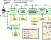 Golden rules for describing business processes
Popular
- Determining the amount of accumulated wear Accumulated wear determined by the multiplicative method
- Responsibilities of the financial director
- International Financial Reporting Standards year
- Job description of financial director
- Legal aspects and issues of demand for project financing Features of project financing of commercial banks
- Organization of budgeting at the enterprise
- Well drilling rates
- Variable frequency asynchronous electric drive - a course of lectures Automated electric drive a course of lectures
- Variable frequency asynchronous electric drive - course of lectures
- Operating instructions for the stand for