Thermal imaging lens. IR lenses
Development, calculation and production of infrared (IR) lenses for thermal imaging systems operating in the ranges of 3…5 and 8…12 µm, as well as for optical sensors operating in the IR range, are an important activity of the company. The company designs and manufactures infrared (IR) lenses (including athermal lenses), both in series in standard design and according to the customer's specifications, and also calculates and manufactures other optical assemblies for IR equipment, including:
- thermal imaging lenses for uncooled thermal imaging cameras based on microbolometric matrices in the range of 8…12 µm. This is the most common type of system, which is due to the effective spectral range for transmitting a thermal image, the optimal practicality of matrix receivers that do not require cooling and a cold diaphragm, as well as the relatively low price of such a device;
- thermal imaging lenses for cooled thermal imaging cameras operating in the range of 3…5 µm. On the basis of such systems, thermal imagers with an increased combination of requirements for characteristics and design are created. This is the most complex type of infrared systems, but at the same time it has the best capabilities for detecting and identifying objects of observation;
- IR lenses for single- and multi-element sensors operating in the mid- and near-IR ranges, mainly 3...5 µm. Usually these are simple systems, which include simple IR optics and a sensor, the main task of which is signal generation, and not image transmission.
Infrared lenses are used in thermal imaging systems of various classes:
- defense (portable and stationary thermal imagers, thermal imaging sights, optical-location stations, target designation devices and sights of ground equipment);
- technological (thermal control devices for technological and construction purposes, pyrometers);
- for security (thermal imaging cameras for perimeter control, borders, fire protection systems).
Depending on the tasks set, we develop infrared (IR) lenses of all the specified classes, among which athermal IR lenses stand out. IR optics for thermal imagers of the medium and long ranges has its own specifics, expressed in the features of the thermooptical characteristics of the optical materials used, such as single crystals of germanium, silicon, polycrystalline zinc selenide and sulfide, single crystals of metal fluorides. In most cases, the IR lens contains lenses made of germanium, which has a high and non-linear temperature coefficient of refraction. In view of this, IR optics are prone to defocus with temperature changes, and one solution to the problem is a thermally compensated design that moves the lens or lens group relative to the receiver depending on temperature. Few companies offer athermal lenses due to the need to develop complex designs often used in harsh mechanical and shock loading conditions. According to your terms of reference, we will calculate and develop a custom-made athermal IR lens. Thermal imager optics are designed and manufactured in various versions using extra hard protective coatings, OEM-version, with a lightweight design.
Do I need additional lenses for the thermal imager?
When buying a thermal imager, everyone asks himself this question and answers it himself, guided by the available information. For our part, we will try to expand the amount of the same information so that the choice of the buyer is more reasonable.
So, why do you need additional lenses/lenses?
The image quality depends on several parameters, but primarily on the quality of the thermal imaging matrix, its sensitivity and size, as well as on the parameters of the lens.
First of all, it is the technical characteristics of the thermal imaging matrix and the lens that determine the quality of the image. As a rule, it is not possible to change the matrix to a large one, so there are only interchangeable or additional lenses that increase the quality of the image. I am quite skeptical about claims that sensor and lens deficiencies can be solved with additional software processing, and thus get more than is possible from hardware.
For example:
A 384x288 sensor with a 20⁰ lens provides a spatial resolution of 0.91 mrad. A 160x120 matrix with the same 20⁰ lens provides a resolution of 2.2 mrad.
In other words, at a distance of 100 meters, a thermal imager with a 384x288 matrix can distinguish an object 9.1x9.1 cm in size, while for a 160x120 matrix, the minimum object must have dimensions of at least 22x22 cm!
The possibility of achieving a resolution of 9x9 cm sounds very optimistic, despite the fact that the quality of the original, even hundreds of shots, is no better than 22x22 cm.
Obviously, the "super resolution" option can somewhat improve the quality of the image, especially in the case of "natural" hand trembling, but the possibility of doing a miracle by doubling the resolution remains at least in doubt.
Thus, one natural way to expand the effective range or area of shooting remains - additional lenses. The standard lens offers two optional lenses - wide-angle and narrow-angle.
wide angle lens is typically used when you want to capture a large area from a relatively short distance. Not as popular as a narrow-angle lens, since you can always combine a series of standard shots into a panoramic image, especially since a wide-angle lens expands the shooting area at the expense of detail, and this suits few.
Narrow (telephoto) lens used in the case when high detail is important for a relatively small object remote at a decent distance. Here, no software tricks can solve the problem - you need a special lens. In my practice, there was a case when it was necessary to shoot a TEC5 pipe (height over 200m), in this case such a lens was simply necessary.
|
Building (distance about 150 meters) |
Thermal Imager Ti175 |
Thermal Imager Ti175 |
|
Ti395 thermal imager |
Thermal imager Ti395 with a matrix (384x288), narrow-angle lens 45mm |
|
|
Roof (distance about 50 meters) |
Thermal imager Ti175 with a matrix (160x120), standard lens |
Thermal imager Ti175 with a matrix (160x120), narrow-angle lens 45mm |
|
Thermal imager Ti395 with a matrix (384x288), standard lens |
Thermal imager |


Infrared radiation is caused by fluctuations in electric charges that make up any substance that makes up objects of living and inanimate nature, namely electrons and ions. The vibrations of the ions that make up the substance correspond to low-frequency radiation (infrared radiation) due to the significant mass of the oscillating charges. The radiation resulting from the movement of electrons can also have a high frequency, which creates radiation in the visible and ultraviolet regions of the spectrum.
Electrons are part of atoms and are held near their equilibrium position (as part of molecules or a crystal lattice) by significant internal forces. Set in motion, they experience irregular braking, and their radiation acquires the character of impulses, i.e. It is characterized by a spectrum of different wavelengths, among which there are low frequency waves, namely infrared radiation.
Infrared radiation is electromagnetic radiation occupying the spectral region between the end of the red region of visible light (with a wavelength (λ) equal to 0.74 μm and microwave radio emission with a wavelength of 1 ... 2 mm.
In the infrared range, there are areas where infrared radiation is intensively absorbed by the atmosphere due to the presence of carbon dioxide, ozone, and water vapor in it.
At the same time, there are also so-called "transparency windows" (a range of wavelengths of optical radiation in which there is less absorption of IR radiation by the medium compared to other ranges). Many infrared systems (including some night vision devices and thermal imagers) are effective precisely because of the existence of such “transparency windows”. Here are some ranges (wavelengths are given in micrometers): 0.95…1.05, 1.2…1.3, 1.5…1.8, 2.1…2.4, 3.3…4.2, 4.5…5, 8…13.
.jpg)
Atmospheric interferences (fog, haze, as well as the opacity of the atmosphere due to smoke, smog, etc.) affect infrared radiation differently in different parts of the spectrum, but with increasing wavelength, the influence of these interferences decreases. This is due to the fact that the wavelength becomes comparable to the size of fog drops and dust particles, so the propagating radiation is scattered to a lesser extent by obstacles and goes around them due to diffraction. For example, in the spectral region of 8…13 µm, fog does not create serious interference with the propagation of radiation.
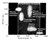
Any heated body emits a stream of infrared radiation, that is, optical radiation with a wavelength that is longer than the wavelength of visible radiation, but less than the wavelength of microwave radiation.
Example. The human body temperature is 36.6°С, its spectral radiation is in the range of 6…21 µm, a metal bar heated to 300°С emits in the wave range from 2 to 6 µm. At the same time, a helix of a tungsten filament heated to a temperature of 2400°C has an emission of 0.2…
- microns, thereby affecting the visible region of the spectrum, which manifests itself as a bright glow.
Spheres of civil application of thermal imaging
Thermal imaging devices for civil use are conditionally divided into two large groups - observation devices and measuring devices. The first includes equipment for security systems and fire safety, thermal imaging systems for transport security, hunting thermal imaging devices and sights, thermal imagers used in forensic science, etc. Measuring thermal imagers are used in medicine, energy, mechanical engineering and scientific activities.

Some examples. According to statistics that are valid for most regions with a developed transport network, more than half of fatal accidents occur at night, while most drivers use a car during the daytime. It is no coincidence that in recent years it has become a common practice to equip cars with a thermal imaging camera, which transmits to a display located in the passenger compartment a temperature picture of the road situation in front of the car. Thus, the thermal imager complements the driver's perception, which is imperfect for many reasons (darkness, fog, oncoming headlights) at night. In the same way, thermal imaging cameras are used in security video surveillance in parallel with digital night cameras (hybrid video surveillance system), which gives a much more complete picture of the nature and behavior of objects in the frame. The Ministry of Emergency Situations use thermal imaging cameras in case of fires - in conditions of smoke in the room, the thermal imager helps in detecting people and sources of combustion. The study of electrical wiring allows you to detect a connection defect. Thermal imaging scanning of forest areas from the air helps to determine the source of the fire.
Finally, portable wearable thermal imagers are successfully used in hunting (detection of animals, effective search for wounded animals without a dog), when conducting quantitative livestock counts, etc. In the future, thermal imagers from the group of observation devices mainly for hunting will be considered.
The principle of operation of the thermal imager
In engineering practice, there are concepts of an object and a background. The object is usually objects that need to be detected and considered (a person, vehicles, animals, etc.), the background is everything else not occupied by the object of observation, the space in the field of view of the device (forest, grass, buildings, etc.)
The operation of all thermal imaging systems is based on fixing the temperature difference of the “object / background” pair and on converting the information received into an image visible to the eye. Due to the fact that all the bodies around are heated unevenly, a certain picture of the distribution of infrared radiation is formed. And the greater the difference in the intensity of the infrared radiation of the bodies of the object and the background, the more distinguishable, that is, the contrast, will be the image received by the thermal imaging camera. Modern thermal imaging devices are capable of detecting a temperature contrast of 0.015 ... 0.07 degrees.
While the vast majority of night vision devices based on image intensifier tubes or CMOS / CCDs capture infrared radiation with a wavelength in the range of 0.78 ... 1 μm, which is only slightly higher than the sensitivity of the human eye, the main The operating range of thermal imaging equipment is 3…5.5 µm (medium-wave infrared, or MWIR) and 8…14 µm (long-wave IR, or LWIR). It is here that the surface layers of the atmosphere are transparent to infrared radiation, and the emissivity of the observed objects with temperatures from -50 to +50ºС is maximum.
A thermal imager is an electronic observation device that builds an image of the temperature difference in the observed region of space. The basis of any thermal imager is a bolometric matrix (sensor), each element (pixel) of which measures the temperature with high accuracy.
The advantage of thermal imagers is that they do not require external sources of illumination - the thermal imager's sensor is sensitive to the objects' own radiation. As a result, thermal imagers work equally well day and night, including in absolute darkness. As noted above, bad weather conditions (fog, rain) do not create insurmountable interference with a thermal imaging device, while at the same time making ordinary night devices completely useless.
Simplistically, the principle of operation of all thermal imagers is described by the following algorithm:
- The lens of the thermal imager forms on the sensor a temperature map (or a map of the radiation power difference) of the entire area observed in the field of view
- The microprocessor and other electronic components of the design read the data from the matrix, process them and form an image on the display of the device, which is a visual interpretation of these data, which is viewed directly or through the eyepiece by the observer.
Unlike night vision devices based on image intensifier tubes (let's call them analog), thermal imagers, like digital night vision devices, allow you to implement a large number of user settings and functions. For example, adjusting the brightness, contrast of the image, changing the color of the image, entering various information into the field of view (current time, low battery indication, icons of activated modes, etc.), additional digital zoom, the “picture in picture” function (allows in a separate a small "window" to display in the field of view an additional image of the entire object or some part of it, including an enlarged one), temporarily turning off the display (to save energy and mask the observer by eliminating the glow of the working display).
To fix the image of the observed objects, video recorders can be integrated into thermal imagers. It is possible to implement such functions as wireless (radio channel, WI-FI) transmission of information (photo, video) to external receivers or remote control of the device (for example, from mobile devices), integration with laser rangefinders (with input of information from rangefinders in the field of view of the device) , GPS-sensors (the possibility of fixing the coordinates of the object of observation), etc.
Thermal imaging sights also have a number of distinctive features in relation to "analogue" night sights for hunting. The aiming mark in them is usually "digital", i.e. the image of the mark during the processing of the video signal is superimposed over the image observed on the display and moves electronically, which makes it possible to exclude from the composition of the sight the mechanical units for inputting corrections that are part of night analog or daytime optical sights and require high precision in the manufacture of parts and assembly of these units. Additionally, this eliminates such an effect as parallax, because. the image of the object of observation and the image of the reticle are in the same plane - the plane of the display.
In digital and thermal imaging sights, it is possible to store in memory a large number of reticles with different configurations and colors, convenient and fast zeroing using the "sighting in with one shot" or "zeroing in Freeze mode", the function of automatically entering corrections when changing the shooting distance , storing zeroing coordinates for several weapons, indication of the inclination (obstruction) of the sight and much more.
Thermal imaging device.

Lens. The most common, but not the only material for the manufacture of lenses for thermal imaging devices is single-crystal germanium. To some extent, sapphire, zinc selenide, silicon and polyethylene also have bandwidth in the MWIR and LWIR bands. Chalcogenide glasses are also used for the manufacture of lenses for thermal imaging devices.
Optical germanium has a high transmission capacity and, accordingly, a low absorption coefficient in the range of 2…15 µm. It is worth recalling that this range captures two atmospheric “transparency windows” (3…5 and 8…12 µm). Most of the sensors used in civilian thermal imaging devices operate in the same range.

Germanium is an expensive material, so optical systems are trying to be made from the minimum amount of germanium components. Sometimes mirrors with spherical or aspherical surfaces are used to reduce the cost of the lens design. To protect the outer optical surfaces from external influences, a coating based on diamond-like carbon (DLC) or analogues is used.
Classical optical glass is not used for the manufacture of lenses for thermal imaging devices, since it does not have a bandwidth at a wavelength of more than 4 microns.
The design of the lens and its parameters have a significant impact on the capabilities of a particular thermal imaging device. So, lens focal length directly affects the magnification of the device (the greater the focus, the greater, ceteris paribus, the magnification), the field of view (decreases with increasing focus) and the observation range. Relative lens aperture, calculated as the quotient of the lens diameter to the focus, characterizes the relative amount of energy that can pass through the lens. The relative aperture index affects the sensitivity, as well as the temperature resolution of the thermal imaging device.
Visual effects such as vignetting and the Narcissus effect are also due to lens design and are common to all thermal imaging devices to some extent.

Sensor. The photosensitive element of a thermal imaging device is a two-dimensional multi-element array of photodetectors (FPA) made on the basis of various semiconductor materials. There are quite a lot of technologies for the production of infrared sensitive elements, however, in thermal imaging devices for civil use, one can note the overwhelming superiority of bolometers (microbolometers).
The microbolometer is an IR energy receiver, the action of which is based on a change in the electrical conductivity of the sensitive element when it is heated due to the absorption of radiation. Microbolometers are divided into two subclasses, depending on whether the IR-sensitive material, vanadium oxide (VOx) or amorphous silicon (α-Si), is used.
The sensitive material absorbs infrared radiation, as a result of which, according to the law of conservation of energy, the sensitive area of the pixel (single photodetector in the matrix) of the microbolometer heats up. The internal electrical conductivity of the material changes, and these changes are recorded. The end result is a monochrome or color visualization of the temperature picture on the display of the device. It should be noted that the color in which the temperature pattern is displayed on the display depends entirely on the operation of the software part of the thermal imaging device.

On the picture: Ulis microbolometric matrix (sensor)
The production of microbolometric matrices is a science-intensive, high-tech and expensive process. There are only a few companies and countries in the world that can afford to maintain such production.
Manufacturers of thermal imaging sensors (microbolometers), in their documents regulating the quality of sensors, allow the presence on the sensor of both individual pixels and their clusters (clusters) that have output signal deviations during normal operation - the so-called "dead" or "broken" pixels . "Broken" pixels are common to sensors from any manufacturer. Their presence is explained by various deviations that can occur during the manufacture of a microbolometer, as well as the presence of foreign impurities in the materials from which the sensitive elements are made. During the operation of a thermal imaging device, the intrinsic temperature of the pixels rises, and pixels that are unstable to temperature increase (“broken”) begin to produce a signal that can differ several times from the signal of correctly working pixels. On the display of a thermal imaging device, such pixels may appear as white or black dots (in the case of individual pixels) or spots of various configurations, sizes (in the case of clusters) and brightness (very bright or very dark). The presence of such pixels does not in any way affect the durability of the sensor and is not a reason for the deterioration of its parameters as it is used in the future. In fact, this is just a "cosmetic" defect in the image.
Thermal imager manufacturers use various software algorithms for signal processing from defective pixels to minimize their impact on image quality and visibility. The essence of processing is to replace the signal from a defective pixel with a signal from a neighboring (nearest) normally functioning pixel or an averaged signal from several neighboring pixels. As a result of such processing, defective pixels, as a rule, become almost invisible in the image.
Under certain observation conditions, it is still possible to see the presence of corrected defective pixels (especially clusters), for example, when the boundary between warm and cold objects enters the field of view of a thermal imaging device, and in this way, when this boundary exactly falls between a cluster of defective pixels and normally operating pixels. When these conditions coincide, the cluster of defective pixels is seen as a spot that shimmers in white and dark colors, and most of all resembles a drop of liquid in the image. It is important to note that the presence of such an effect is not a sign of a defective thermal imaging device.
Block of electronic processing. Typically, an electronic processing unit consists of one or more boards (depending on the layout of the device), on which specialized microcircuits are located that process the signal read from the sensor and then transmit the signal to the display, where an image of the temperature distribution of the observed area is formed. The main controls of the device are located on the boards, and the power supply circuit is also implemented, both for the device as a whole and for individual circuits of the circuit.
Microdisplay and eyepiece. Due to the fact that most hunting thermal imagers use microdisplays, an eyepiece is used to observe the image, which works like a magnifying glass and allows you to comfortably view the image with magnification.
The most commonly used liquid-crystal (LCD) displays are transmissive (the back side of the display is illuminated by a light source) or OLED displays (when an electric current is passed, the display substance begins to emit light).
The use of OLED displays has a number of advantages: the ability to operate the device at lower temperatures, higher image brightness and contrast, a simpler and more reliable design (there is no source for backlighting the display, as in LCD displays). In addition to LCD and OLED displays, LCOS (Liquid Crystal on Silicone) microdisplays, which are a type of reflective type liquid crystal displays, can be used.
MAIN PARAMETERS OF THERMAL IMAGE DEVICES
INCREASE.The characteristic shows how many times the image of the object observed in the device is larger compared to the observation of the object with the naked eye. Unit of measure - multiple (designation"x", for example, "2x" - "two times").
For thermal imaging devices, typical magnifications are between 1x and 5x, as The main task of night devices is to detect and recognize objects in low light and bad weather conditions. An increase in magnification in thermal imaging devices leads to a significant decrease in the overall aperture of the device, as a result of which the image of the object will be less contrasting with respect to the background than in a similar device with a lower magnification. The drop in aperture ratio with increasing magnification can be compensated by an increase in the light diameter of the lens, but this, in turn, will lead to an increase in overall dimensions and weight of the device, complicating optics, which reduces the overall usability of portable devices and significantly increases the price of a thermal imaging device. This is especially important for scopes, as users additionally have to hold the weapon in their hands. At high magnification, there are also difficulties in finding and tracking the object of observation, especially if the object is in motion, since with an increase in magnification, the field of view decreases.
The magnification is determined by the focal lengths of the lens and the eyepiece, as well as the zoom factor (K), equal to the ratio of the physical dimensions (diagonals) of the display and sensor:

where:
fabout- lens focal length
fOK- focal length of the eyepiece
LWith- sensor diagonal size
Ld- display diagonal size.
DEPENDENCIES:
The longer the lens focal length, the display size, the more magnification.
The larger the focal length of the eyepiece, the sensor size, the the increase is less.
LINE OF SIGHT. It characterizes the size of the space that can be simultaneously viewed through the device. Usually, the field of view in the parameters of devices is indicated in degrees (the angle of the field of view in the figure below is indicated as 2Ѡ) or in meters for a specific distance (L) to the object of observation (the linear field of view in the figure is indicated as A).

The field of view of digital night vision devices and thermal imaging devices is determined by the focus of the lens (fob) and the physical size of the sensor (B). Usually, the width (horizontal size) is taken as the sensor size when calculating the field of view, as a result, the horizontal angular field of view is obtained:

Knowing the size of the sensor vertically (height) and diagonally, it is also possible to calculate the angular field of view of the device vertically or diagonally.
Addiction:
The larger the sensor size or the smaller the focus of the lens, themore field of view.
The larger the field of view of the device, the more comfortable it is to observe objects - there is no need to constantly move the device to view the area of interest.
It is important to understand that the field of view is inversely proportional to the increase - as the magnification of the device increases, its field of view decreases. This is also one of the reasons why infrared systems (thermal imagers in particular) are not produced with high magnification. At the same time, you need to understand that with an increase in the field of view, the detection and recognition distance will decrease.
FRAME REFRESH RATE. One of the main technical characteristics of a thermal imaging device is the frame refresh rate. From the user's point of view, this is the number of frames shown on the display in one second. The higher the frame refresh rate, the less noticeable the effect of "lag" of the image generated by the thermal imaging device in relation to the real scene. So, when observing dynamic scenes with a device with a refresh rate of 9 frames per second, the image may seem blurry, and the movements of moving objects may be delayed, with “jerks”. Conversely, the higher the frame refresh rate, the smoother the display of dynamic scenes will be.
PERMISSION. FACTORS AFFECTING RESOLUTION.
The resolution is determined by the parameters of the optical elements of the device, sensor, display, the quality of circuit solutions implemented in the device, as well as the applied signal processing algorithms. The resolution of a thermal imaging device (resolution) is a complex indicator, the components of which are temperature and spatial resolution. Let's consider each of these components separately.
Temperature resolution(sensitivity; minimum detectable temperature difference) is the boundary ratio of the signal of the object of observation to the background signal, taking into account the noise of the sensitive element (sensor) of the thermal imaging camera. High temperature resolution means that a thermal imaging device will be able to display an object of a certain temperature against a background with a similar temperature, and the smaller the difference between the temperatures of the object and the background, the higher the temperature resolution.
Spatial resolution characterizes the ability of the device to display separately two closely spaced points or lines. In the technical characteristics of the device, this parameter can be written as “resolution”, “resolution limit”, “maximum resolution”, which, in principle, is the same thing.
Most often, the resolution of the device characterizes the spatial resolution of the microbolometer, since the optical components of the device usually have a resolution margin.
As a rule, resolution is indicated in strokes (lines) per millimeter, but can also be indicated in angular units (seconds or minutes).
The higher the resolution value in strokes (lines) per millimeter and the lower it is in angular terms, the higher the resolution. The higher the resolution of the device, the clearer the image is seen by the observer.
To measure the resolution of thermal imagers, special equipment is used - a collimator, which creates an imitation image of a special test object - a dashed thermal world. Looking at the image of the test object through the device, the resolution of the thermal imager is judged - the smaller the strokes of the worlds can be clearly seen separately from each other, the higher the resolution of the device.

Image: Various options for the thermal world (view in a thermal imaging device)
The resolution of the instrument depends on the resolution of the objective and the eyepiece. The lens forms an image of the object of observation in the sensor plane, and in case of insufficient resolution of the lens, further improvement in the resolution of the device is impossible. In the same way, a poor-quality eyepiece can "spoil" the clearest image formed by the instrument's components on the display.
The resolution of the device also depends on the parameters of the display on which the image is formed. As in the case of the sensor, the display resolution (number of pixels) and their size are of decisive importance. Pixel density in a display is characterized by such an indicator as PPI (short for English "pixels per inch") - this is an indicator that indicates the number of pixels per inch of area.

In the case of direct image transfer (without scaling) from the sensor to the display, the resolutions of both should be the same. In this case, the decrease in the resolution of the device (if the display resolution is less than the resolution of the sensor) or the unjustified use of an expensive display (if the display resolution is higher than that of the sensor) is excluded.
The sensor parameters have a great influence on the resolution of the device. First of all, this is the resolution of the bolometer - the total number of pixels (usually indicated as the product of pixels in the line and in the column) and the pixel size. These two criteria provide the main resolution score.
ADDICTION:
The larger the number of pixels and the smaller their size, the higherresolution.
This statement is true for the same physical sizesensors. A sensor that has a pixel density per unit arealarger, has a higher resolution.
Thermal imaging devices can also use various signal processing algorithms that can affect the overall resolution of the device. First of all, we are talking about "digital zooming", when the image formed by the matrix is digitally processed and "transferred" to the display with some increase. In this case, the overall resolution of the device is reduced. A similar effect can be observed in digital cameras when using the "digital zoom" function.
Along with the above factors, we should mention a few more that can reduce the resolution of the device. First of all, these are various kinds of “noise” that distort the useful signal, and ultimately degrade the image quality. The following types of noise can be distinguished:
Dark Signal Noise. The main reason for this noise is thermionic emission of electrons (spontaneous emission of electrons as a result of heating of the sensor material). The lower the temperature, the lower the dark signal, i.e. less noise, it is to eliminate this noise that a shutter (tent) and calibration of the microbolometer are used.
Read Noise. When the signal accumulated in the sensor pixel is output from the sensor, converted to voltage, and amplified, additional noise appears in each element, called readout noise. To combat noise, various image processing software algorithms are used, which are often called noise reduction algorithms.
In addition to noise, resolution can be significantly reduced by interference due to device layout errors (mutual arrangement of printed circuit boards and connecting wires, cables inside the device) or due to errors in PCB routing (mutual arrangement of conductive tracks, the presence and quality of shielding layers ). Also, errors in the electrical circuit of the device, incorrect selection of radio elements for the implementation of various filters, and in-circuit power supply of the electrical circuits of the device can also cause interference. Therefore, the development of electrical circuits, writing software for signal processing, board routing are important and complex tasks in the design of thermal imaging devices.
OBSERVATION RANGE.
The range of observation of an object using a thermal imaging device depends on a combination of a large number of internal factors (parameters of the sensor, optical and electronic parts of the device) and external conditions (various characteristics of the observed object, background, purity of the atmosphere, and so on).
The most applicable approach to describing the range of observation is its division into the ranges of detection, recognition and identification, described in detail in various sources, according to the rules defined by the so-called. the Johnson criterion, according to which the observation range is directly related to the temperature and spatial resolution of a thermal imaging device.
For further development of the topic, it is required to introduce the concept of the critical size of the object of observation. The critical size is considered to be the size along which the object image is analyzed to identify its characteristic geometric features. Often, the minimum visible size of the object along which the analysis is carried out is taken as the critical one. For example, for a wild boar or roe deer, the height of the body can be considered a critical size, for a person - height.
The range at which the critical size of a certain object of observation fits into 2 or more pixels of the thermal imager sensor is considered to be detection range. The fact of detection simply shows the presence of this object at a certain distance, but does not give an idea of its characteristics (does not allow to say what kind of object it is).
Fact recognition object, the ability to determine the type of object is recognized. This means that the observer is able to distinguish what he is observing at the moment - a person, an animal, a car, and so on. It is generally accepted that recognition is possible provided that the critical size of the object fits at least 6 pixels of the sensor.
From the point of view of hunting application, the greatest practical utility is identification range. By identification it is understood that the observer is able to evaluate not only the type of object, but also to understand its characteristic features (for example, a male wild boar 1.2 m long and 0.7 m high). To fulfill this condition, it is necessary that the critical size of the object is covered by at least 12 pixels of the sensor.
It is important to understand that in all these cases we are talking about a 50% probability of detecting, recognizing or identifying an object of a given level. The more pixels overlap the critical size of an object, the higher the probability of detection, recognition or identification.
EXIT PUPILE REMOVAL- this is the distance from the outer surface of the last lens of the eyepiece to the plane of the pupil of the observer's eye, at which the observed image will be the most optimal (maximum field of view, minimum distortion). This parameter is most important for sights, in which the removal of the exit pupil should be at least 50 mm (optimally - 80-100 mm). Such a large removal of the exit pupil is necessary to prevent injury to the shooter by the eyepiece of the sight during recoil. As a rule, for night vision devices and thermal imagers, the distance of the exit pupil is equal to the length of the eyecup, which is necessary to mask the glow of the display at night.
THERMAL VISION SENSOR CALIBRATION
Calibration of a thermal imaging device is divided into factory and user calibration. The production process of thermal imaging devices based on uncooled sensors provides for factory calibration of the device (a pair of "lens - sensor") using special equipment.
You can familiarize yourself with the new models of PULSAR thermal imagers and make an informed choice.


Popular
- What is gypsum and where is it mined
- How a nuclear power plant works
- The simplest clay dishes in survival conditions!
- Ao Kamov. Light helicopters of Russia. Production of light helicopters in Russia Where light helicopters are used
- Children's electronic presentations and clips Children's electronic presentations for preschoolers
- How to make a do-it-yourself collage of photos: ideas, methods and design examples Funny do-it-yourself photo collage
- How to make a collage of photos with your own hands on the wall: create home comfort Collage of family photos with your own hands
- Funny fairy tale scene about a turnip Fairy tale turnip for the new year for children
- Prom theme: how to choose and what ideas do you have?
- Batman comics: where to start reading?