Yaw damper. Principles of Flight Oxford Aviation Academy
Wing sweep.
As shown in the figure, the sliding changes the effective sweep of the swept wing half-wings. If a wing is producing lift, then a half-wing with less effective sweep will generate more force than the opposite half-wing. This will give a stabilizing roll moment. Thus, The swept wing increases the lateral stability of the aircraft.(Swept back wing reduces lateral stability).

The influence of the sweep is proportional to C y and the sweep angle of the wing . The figure shows that with the same sliding, the difference in the lift forces of the half-wings increases with increasing C y (decreasing speed). Because high-speed aircraft require swept wings, they exhibit excessive lateral stability at low speeds.
Swept wing aircraft need a smaller transverse V wing than straight wing aircraft.

Keel creates a small stabilizing roll moment when sliding. Since the point of application of the keel lateral force is above the center of gravity, the keel lateral force, providing directional stability, also plays a small role in the lateral stability of the aircraft.
ventral ridge located below the center of gravity and therefore has a negative effect on lateral stability.

In general, lateral stability should not be too great. Excessive aircraft roll response to slip can result in dutch pitch oscillations or require the aircraft's lateral control system to be very efficient for crosswind takeoffs and landings.
If the aircraft demonstrates satisfactory lateral stability in cruise flight, then there are slight deviations from the norm during takeoff and landing. Since the influence of flaps and engine thrust is destabilizing, it is possible to reduce stability due to their influence.

The extension of the flaps makes the inner sections of the wing more efficient, and since they are closer to the center of gravity, the resulting moment from the change in the lift forces of the semi-wings is reduced.
The influence of engine thrust in jet aircraft is insignificant, but significant in propeller-driven aircraft.
Power blowing of the inner sections of the wing at low flight speeds makes them much more efficient than the outer sections, which reduces lateral stability.
Combining the effect of flaps and power blowing of the propeller can lead to a significant decrease in lateral stability in the takeoff and landing modes of propeller-driven aircraft.
The aircraft must be lateral stable, but the stability must not be great. In addition, some exceptions are allowed for takeoff and landing modes.
The problems that arise from over-resilience are significant and difficult to deal with.
The pilot feels the lateral stability through the necessary deflection of the steering wheel (control stick) to maintain a given roll in the event of an aircraft slip (lateral gust, pedal deflection, asymmetric engine thrust, etc.). In the presence of lateral stability, the pilot will be forced to deflect the steering wheel in the direction of the resulting slip (the side opposite to the deflected pedal).
Conclusion: The designer is faced with a dilemma. To increase the flight speed, a swept wing is installed on the aircraft, but this increases its lateral stability. To reduce it, reduce the transverse V of the wing. With the upper wing on the fuselage, there is an additional effect that enhances lateral stability. To combat this, a negative V wing is used.
Dynamic interaction of track and cross movement.
In the previous review, the response of the aircraft to roll and yaw was considered in isolation, for detailed analysis.
In reality, both of these moments occur simultaneously: the heeling moment from lateral static stability and the yaw moment from directional static stability.
Spiral instability.
An aircraft exhibits helical instability if its directional stability is very high compared to lateral stability.
Spiral instability manifests itself smoothly. The aircraft, after being affected by the disturbance, begins to gradually increase the roll, which can gradually turn into a steep downward spiral.
The reason for the occurrence of helical instability is that the aircraft quickly eliminates the resulting slip, while the weak lateral stability does not have time to remove the roll. In this case, the moment of lateral stability is counteracted by the helical roll moment, which occurs when the aircraft rotates about the normal axis. Suppose there is a slip on the right. The directional stability begins to turn the nose of the aircraft to the right. In this case, the left wing moves along a larger radius, its lifting force increases and tends to roll the aircraft to the right - as opposed to the moment of lateral stability.
The rate of roll development during helical instability is usually weak, which does not create difficulties for the pilot in controlling the aircraft.
"Dutch Step".
Dutch pitch oscillations occur when the aircraft's lateral stability is greater than its directional stability.
These are spontaneously occurring unwanted vibrations caused by the interaction of the track and transverse channel.
When an aircraft has a slip, the roll moment vigorously creates a roll against the slip. On a rising half-wing, the lift and inductive drag are greater than on a descending half-wing. This creates a yaw moment to reduce the slip angle, but due to inertia, the aircraft overshoots the zero value and slip occurs on the other side. Then the process is repeated on the other side.
To eliminate Dutch pitch, aircraft are equipped with yaw dampers that artificially increase directional stability by deflecting the rudder to counteract the resulting yaw rate.
If the yaw damper fails in flight, then it is recommended to eliminate the resulting oscillations using the lateral control of the aircraft. Because when using the rudder, the delay in the reaction of the aircraft is such that it is possible for the pilot to swing the aircraft (PIO). In this case, the "Dutch step" can quickly lead to diverging oscillations and loss of control of the aircraft.
"Dutch pitch" is undesirable, and helical instability is acceptable if the rate of roll rise is low. Therefore, the degree of lateral stability should not be large.
If the degree of aircraft directional stability is sufficient to prevent the "Dutch step", then it is automatically sufficient to prevent directional aperiodic instability (continuous increase in the slip angle). Since the best flight properties are demonstrated by aircraft with a high degree of directional stability and the minimum required degree of lateral stability, most aircraft have a small helical instability. As already mentioned, weak helical instability is of little concern to pilots and is much more preferable than the "Dutch step".
The swept wing significantly affects the lateral stability. Since the degree of this influence depends on C y, the dynamic characteristics of the aircraft may vary depending on the flight speed. At high speeds (small C y), the lateral stability is low and the aircraft has helical instability. At low speeds, lateral stability increases and the tendency to "Dutch step" oscillations increases.
Pilot swing (PIO).
Certain unwanted vibrations of the aircraft may be due to unintentional movements of the aircraft controls. Oscillations can occur about any axis, but short-period longitudinal oscillations are the most dangerous. Due to feedback delay, the pilot/control system/aircraft system can excite vibrations leading to structural failure and loss of control.
When the pilot's reaction time and control system lag coincide with the aircraft's natural oscillation period, unintended pilot control responses can lead to a sharp increase in oscillation amplitude. Since these oscillations are relatively high frequency, the amplitude can reach dangerous values in a very short period of time.
When entering this flight mode, the most effective action is to release the controls. Any attempt to forcibly stop the oscillations will only continue the excitation and increase its magnitude. The release of the controls eliminates the cause of the excitatory vibrations and allows the aircraft to exit the mode due to its own dynamic stability.
Flying at high M numbers.
Usually, flight at high M numbers occurs at high altitude. Consider the effect of high altitude on the behavior of the aircraft. Aerodynamic damping is manifested in the appearance of moments of forces that prevent the aircraft from rotating about its three axes. The reason for the appearance of these moments is the change in the angles of flow around the wing, stabilizer and keel during the rotation of the aircraft.
The greater the true speed of the aircraft, the smaller the changes in the flow angles at a given angular velocity of rotation, and, accordingly, the less damping. The amount of damping reduction is proportional to the square root of the relative air density. The indicated ground (EAS) and true (TAS) speeds are in the same proportion. So, for example, in a standard atmosphere at 40,000 feet, the damping will be half that at sea level.
Ensuring velocity stability on transonic M numbers.
When the number M of flight exceeds M crit, a supersonic zone with a shock wave is formed above the upper surface of the wing. This leads to:
displacement of the center of pressure of the wing back, and
reduction of the flow bevel behind the wing.
To maintain the required speed gradient at the helm, a device that compensates for this moment (Mach trim) is built into the control system of modern aircraft.
By increasing the M number, this device can:
deflect the elevator up;
move the deflectable stabilizer toe down, or
shift the center of gravity of the aircraft by pumping fuel into the rear tank.
Which method is used depends on the aircraft manufacturer. This system regulates the forces in the longitudinal control channel and works only at large M numbers.
Conclusion
Stability is a quality inherent in an aircraft and allowing it to return to its original flight mode under the influence of disturbances. There are two types of stability - static and dynamic. In each of these modes, the aircraft can be stable, neutral or unstable.
Static stability describes the initial reaction of an aircraft to a deviation from equilibrium about one or more axes (an aircraft has three axes of rotation).
An aircraft is statically stable if, when deviating from the state of equilibrium, it has a tendency to return to its original state.
An aircraft is statically neutral if, when deviating from the state of equilibrium, it does not develop any tendency, and it remains in the new state.
An aircraft is statically unstable if, when deviating from the state of equilibrium, it tends to further increase the deviation. This is a highly undesirable property that can lead to loss of control of the aircraft.
Most aircraft are statically stable in pitch and yaw and are close to statically neutral in roll.
If the aircraft has static stability, then dynamic stability considers the time process of the aircraft's behavior after the disturbance ceases. In the process of returning to the equilibrium state, the aircraft overshoots the initial position by inertia, which creates a deviation in the other direction, and the process is repeated.
If the aircraft is dynamically stable, then these oscillations are damped. The aircraft must be dynamically stable.
If the aircraft is dynamically neutral, then the oscillations will not decay. Dynamic neutrality is an undesirable phenomenon.
If the amplitude of aircraft oscillations increases with time, then this aircraft is dynamically unstable, which is highly undesirable.
The stability (or instability) of an aircraft is determined by the shape and dimensions of its surfaces.
The keel is the main surface that provides directional stability. The stabilizer provides longitudinal stability, and the wing provides transverse stability.
The location of the center of gravity also affects stability. If the center of gravity is near the extreme rear boundary, then the aircraft will be less stable in pitch and yaw. When the center of gravity shifts forward, stability increases.
Although the aircraft is less stable when centered astern, its flight performance is improved due to the reduction of downward force on the stabilizer (balance loss). Such an aircraft has a slightly lower stall speed, less drag, and a higher cruising speed on the same engine mode.
Maneuverability is the quality of an aircraft that allows it to easily maneuver and withstand the stresses associated with that maneuver.
Controllability is the ability of the aircraft to respond to the pilot's control actions, in particular, to control the attitude and flight path.
An airplane is pitch stable if it returns to level flight after the disturbance caused by vertical gust or elevator deflection has ceased. The position of the center of gravity and the effectiveness of the stabilizer have a major impact on stability and pitch control.
Increasing stability, along any of the axes:
reduces maneuverability and controllability, and
increases efforts on the steering wheel (control handle, pedals).
An aircraft will decrease bank after an accidental roll if it has static roll stability. Lateral stability in English texts is often called the "dihedral effect" (the effect of the transverse V wing).
Most aircraft have a positive V wing. This means that the wingtips are higher than the wing butt. If a left roll occurs in flight, then under the action of the lateral component of gravity, the aircraft will begin to slide to the left. The local angle of attack of the left wing will increase, and that of the right wing will decrease. This will create a moment that brings the plane out of roll.
The swept wing provides more M crit, in addition, it also gives the aircraft lateral stability. In this case, it's a by-product. Swept wing aircraft have a smaller positive V wing than straight wing aircraft.
The overhead wing also enhances lateral stability, so high-wings do not require a positive V wing, but often do the opposite, a negative V wing.
Excessive transverse static stability leads to dynamic instability - oscillations of the "Dutch step" type.
Static directional stability (vane) is the tendency of an aircraft to turn its nose in the direction of the oncoming flow (in the plane of the wings). It is provided by the fact that the lateral area of the aircraft (including the keel) behind the center of gravity is greater than the area ahead of the center of gravity.
The swept wing also increases directional stability.
Excessive static directional stability leads to dynamic instability - the tendency of the aircraft to spiral instability.
Interaction of lateral and directional stability. When the aircraft rolls, it begins to slide onto the lowered half-wing. The directional stability creates a moment for retracting the slip (turning the nose towards the lowered semi-wing), and the transverse stability creates a moment for retracting the roll.
If the directional stability is strong and the lateral stability is weak, then the aircraft will begin to rotate about the normal axis with a sluggish tendency to reduce roll. A semi-wing with a larger radius will flow around at a higher speed, which creates a moment to increase the roll. This moment is called the helical roll moment. If it exceeds the lateral stability moment, then the roll will continuously increase, and since the vertical component of the lift force becomes less than the weight, the aircraft will enter a downward spiral.
If the lateral stability is strong and the directional stability is weak, then the aircraft will tend to oscillate like "Dutch step".
The system for ensuring stability in speed at large numbers of M (Mach trim) maintains a given gradient of efforts in speed. The system regulates the loading of the steering wheel (control stick) and works only at large M numbers.
A yaw damper is installed in the rudder control system to improve the characteristics of the lateral movement of the aircraft and prevent undamped oscillations of the "Dutch pitch" type.
"Dutch roll" (Dutch roll) appears as a result of relatively poor directional stability and excessive lateral stability of the aircraft. When the aircraft rotates about the longitudinal axis, sliding spontaneously occurs towards the descending wing, due to the emerging lateral component of gravity. This immediately leads to the emergence of a moment of transverse stability M x β , which tends to reduce the resulting roll. On aircraft with high lateral stability, it can be significant.
At the same time, the directional stability moment M y β also arises, tending to turn the nose of the aircraft in the direction of the resulting slip. Since directional stability is much weaker than lateral stability on many aircraft, slip recovery lags behind roll recovery. The aircraft, by inertia, skips the position without a roll and begins to roll in the opposite direction. Thus, the aircraft, without intervention in the control, will perform undamped oscillations in roll and slip.
The yaw damper artificially increases directional stability and thus prevents vibrations.
The sensitive element of the yaw damper is a two-stage gyroscope that responds to the angular velocity ω y relative to the normal Y axis. This signal is filtered and amplified depending on the flight speed by a signal from a computer that calculates the altitude-speed parameters (Air Data Computer). Further, the signal is sent to the damper control spool (see the diagram of the main steering gear of the launch vehicle in the "Travel control" section). The spool controls the movement of the damper actuator, which shifts the center of rotation of the primary and secondary summation arms and, thus, is added to the movement of the pedals from the pilots and leads to the movement of the rod of the main rudder drive.
In this case, the movements of the damper actuator are not transmitted to the pedals, and the pilot cannot tactilely feel the operation of the damper. To control its operation, an indicator is displayed showing deviations of the damper actuator.
Convenient control on taxiing: the bar should initially deviate in the direction opposite to the turn. The bar can then return to neutral or even deviate in the direction of the reversal. This is due to the complex law of rudder deflection, when the rudder responds to a rapidly changing component of the angular rate of turn and does not respond to its constant component.
During normal operation of the damper in flight, the deflection of the indicator bar is almost imperceptible.
On new aircraft with an integrated communication unit (IFSAU) installed between the ACS and the aircraft (see Automatic control system), with the flaps extended, the damper signal is increased by 29% to counteract the increasing lateral stability. In addition, 8 hertz signals are attenuated by 50% to reduce vibration and improve passenger comfort.
Coordinated sliding
Coordinated slip is a control maneuver performed during aircraft flight tests. It makes it possible to reveal the features of the lateral stability and controllability of the aircraft, in particular, the mutual effectiveness of the lateral and directional control. When it is performed, a straight flight is maintained at a constant height and speed with a gradual stepwise deflection of the rudder. To prevent the resulting slip from taking the aircraft off the straight path, a roll is created in the opposite direction. Thus, the lateral component of gravity will compensate for the lateral force from sliding. In this maneuver, the travel channel, as it were, is struggling with the transverse one. If there are no strength restrictions, then the rudder deflections are carried out to full flow. As a rule, the pedals are the first to stop, and the lateral control still has a margin. But the opposite also happens.
In an investigation report into the Boeing 737-200 crash on March 3, 1991 in the Colorado Springs area, the NTSB published the results of coordinated slides performed at 150-160 knots in various flap configurations from 40 to 10 degrees.
The case of full deflection (involuntary withdrawal) of the rudder to the right by 25 degrees was considered.
Thus, the table shows that the withdrawal of the rudder to the extreme position is not dangerous when the flaps are released to the position from 40 to 25 degrees. The heeling moment from the resulting sliding can be parried by deflecting the steering wheel at an angle, respectively, from 35 to 68 degrees. This is explained by the sharply increased efficiency of spoilers deflected in flight (flight spoilers), which disrupt the flow from the flap on the half of the wing that should be lowered.
With a flap extension angle of less than 25 degrees, the full deflection of the helm is not enough to parry the rudder pull (at the speed of the experiment - 150-160 knots). So with flaps 15 balancing was achieved only at d РН =23 degrees, with flaps 10 - at d РН =21 degrees.
The bottom line of the table does not apply to coordinated sliding. In this case, balancing was achieved when performing a turn to the right with a roll of 40 degrees. In this case, the steering wheel was deflected to the left by a full angle, and a decrease in the slip angle from 16 to 13 degrees is achieved due to the appearance of a damping ground moment M Y w y from the angular velocity of the turn.
Also in this report there is information that behavioral studies have shown that when the speed decreases to a certain value, the effectiveness of lateral control, with flaps extended by 1 degree, becomes insufficient to parry the withdrawal of the rudder to the extreme position. This speed is called the "critical point speed" (crossover airspeed).
Automatic control system
The automatic aircraft control system (AFCS) consists of three independent systems: the digital flight control system (DFCS), the yaw damper (see Lateral stability and control), and the autothrottle. These systems provide automatic stabilization of the aircraft in pitch, roll and slip and control of the aircraft by signals from radio navigation aids, on-board navigation computer (FMC), altitude and speed parameters computer (ADC) and course stabilization.
The connection between the digital control system and the aircraft is carried out, depending on the configuration of the aircraft, by the communication center (AFC) or the integrated communication center (IFSAU). Depending on this, the operation of the yaw damper changes somewhat.
Automatic control of the aircraft is carried out by means of the elevator and ailerons. Aircraft of the NG modification can be equipped with automatic rudder control.
Also, there is an automatic removal of forces from the steering wheel in the longitudinal channel (with the steering column returning to the neutral position) by rearranging the stabilizer. There is no automatic force relief in the transverse channel, so it is forbidden to use the aileron trim mechanism when the autopilot is on. In this case, the steering machine of the autopilot will overpower the spring of the loading mechanism (aileron feel and centering unit) and, when the autopilot is turned off, the aircraft will begin to roll unexpectedly for the pilot.
A similar incident occurred on September 6, 2011 at the ANA airline, although there the pilot, by involuntarily deflecting the rudder trim mechanism, unbalanced the track channel, which led to the autopilot being turned off and the aircraft to roll sharply.
In flight, with the autopilot engaged, the control column and steering wheel must be in neutral. This indicates the absence of effort in the wiring of the elevator and ailerons. Deviation of the steering column from neutral is a sign of failure of the control of the stabilizer or its departure (runaway).
The deviation of the steering wheel indicates the transverse (track) asymmetry of the aircraft, uneven fuel consumption or asymmetric engine thrust. The lateral channel trim technique is described in the lateral stability and control section.
In the case of flight with asymmetric engine thrust, the pilot must independently control the track channel by deflecting the pedals. Otherwise, the accuracy of maintaining the specified flight parameters is not guaranteed.
Autopilot disengagement (DFCS) is indicated by flashing red A/P P/RST button lamps and a siren sound, and autothrottle disengagement is indicated only by the red A/T P/RST button lamps. According to the AAIB (Air Accidents Investigation Branch) report on the investigation of the Thomsonfly Boeing 737-300 incident in Bournemouth (UK) on September 23, 2007, the absence of an audible autothrottle disengagement alarm was a contributing factor to the incident. During the landing approach, when the engines were running in the “Small throttle” mode, the autothrottle turned off, which went unnoticed by the crew. On the glideslope, the aircraft lost speed to 82 knots (20 km/h below V REF) and entered the stall mode.
In addition to aircraft control, the digital flight control system (DFCS) indicates to the pilots the deviations of the director bars in roll and pitch. These deviations are equivalent to commands to the steering machines of the autopilot. Therefore, when the autopilot is turned off, and the pilot is piloting the aircraft along the directorial bars, he is doing the work of the autopilot steering machine. Piloting by directors significantly increases the accuracy of maintaining the specified modes, but wean the pilot from scanning and analyzing instrument readings, that is, it contributes to the degradation of flight skills. This is facilitated by the policy of airlines, which, in the name of passenger comfort, forbid their pilots to fly with the directors turned off, even in simple weather conditions. The problem of the loss of flight crew skills in aircraft control when automation is turned off has been repeatedly raised at international conferences on flight safety, but things are still there.
Airplane flight under asymmetrical thrust
Consider the behavior of the aircraft immediately after the failure of one of the engines and the required control (balancing) to ensure straight flight with one engine stopped.
Let the left engine fail. The yaw moment M U DV will begin to act on the aircraft, turning it to the left. There will be a slip on the right wing, and, consequently, a roll moment Mx b towards the wing with the engine stopped. The figure shows an approximate change in slip and roll angles when the left engine is stopped.

Because there is a lot of lateral stability (especially with the flaps extended), the bank will be violent, requiring immediate pilot intervention. To parry the heeling moment, when the engine is running in takeoff mode, the full roll deflection of the steering wheel is not enough. It is necessary to remove the slip of the rudder.
Let's consider what are the balancing conditions in a long flight with one idle engine. Let's analyze two specific cases of balancing in straight flight with the engine stopped: 1) without roll, 2) without sliding, as well as the recommendation of Boeing.
1. Fly without roll.

To balance without a roll, it is required to create a slip on the left wing. Then, to the moment from the asymmetric thrust Mu dvig, the moment from sliding Mu b will be added. Their balancing requires a large deflection of the rudder. The lateral forces from the rudder Z rn and from the slip Z b will act in opposite directions and will balance at a certain angle of slip. The transverse moment Mx b will be compensated by the moments from the rudder Mx rn and the ailerons Mx eler.
It would seem that for a pilot a straight flight without a roll is the most acceptable, but due to the large required angle of deflection of the rudder, the resistance of the aircraft increases. This degrades the performance of the aircraft, especially in the event of an engine failure during takeoff with a large mass and at high temperatures.
Note that although the flight takes place here with slip, but the glide indicator ball will be located strictly in the center. The fact is that the aerodynamic forces in this case are located in the plane of symmetry of the aircraft. Generally speaking, this device is not a slip indicator, but a lateral overload indicator. Lateral g-force arises from the uncompensated aerodynamic force Z, which is balanced by the lateral component of gravity G*sing when flying with a roll or centrifugal force when turning the aircraft.
2. Flight without sliding.

The turning moment from the engine Mu dvig is balanced by the moment from the rudder M rn. The lateral force Z pH is balanced by the lateral component of gravity G*sing, when creating a roll on the right wing. The transverse moment from the rudder Mx rn is balanced by the moment from the ailerons Mx eler. Note the aileron deflection in the opposite direction, compared to balancing without a roll. The ball in this case will be deflected towards the lowered wing, although there will be no slip.
This balancing mode is the most beneficial for aircraft energy, since it provides minimal resistance. But the exact maintenance of the regime is problematic. Firstly, pilots do not have an indication of the slip angle, and secondly, when the thrust of a running engine changes, the turning moment changes, which means that the required rudder deflection changes, and the lateral force of the rudder changes accordingly, and hence the required roll angle to compensate for it. Flight manuals for Soviet aircraft gave pilots an approximate figure of 3 to 5 degrees of roll per engine running.
Boeing gives a different criterion for control. Consider the balancing diagram in case of failure of the left engine.

On it, the numbers 1 and 2 show the considered cases of balancing without roll and without slip. However, there are an infinite number of other balancing positions. Boeing recommends that pilots balance the aircraft with zero aileron deflection (level the control wheel). It is written that in this case there is a slight roll on the running engine and the ball is slightly deflected in the same direction. As can be seen from the balancing diagram, this position is something in between the two considered cases of balancing. It is convenient to maintain it, because to control the “horizontality” of the steering wheel it is not even necessary to look into the cockpit and you can control the correct position of the rudder with tactile sensations of the hand. Which half of the steering wheel is lowered means that the pedals must be deflected in the same direction for balancing. Exactly the same piloting technique with the autopilot on, since the pedals from the autopilot are not controlled.
Failsafe
Failsafe refers to the analysis of the impact of malfunctions on the behavior of the aircraft and the ability to safely complete the flight.
When investigating the crash on March 3, 1991, the NTSB assessed the roll deflection required to counteract the following control system failures:
1. Retractable slat section or Krueger slat not extended. In turbulent conditions, this failure is likely to go unnoticed.
2. Failure of the yaw damper with the rudder pulled by 2 degrees. (The maximum angle of deviation of the rudder from the yaw damper on series (300-500) is 3 degrees). Parrying requires a 20-degree yoke deflection.
3. "Floating" spoiler-aileron.
(The lowered spoiler is held in flight by a hydraulic system. If the spoiler retention system fails, then it, due to rarefaction above the wing, can rise above the surface of the wing. This is called "floating".)
Parrying such a failure requires a deflection of the helm by 25 degrees.
4. Steering rudder spool causing 10.5 degrees of rudder deflection. Requires 40 degree steering wheel deflection.
5. Parrying asymmetric engine thrust with 8 degrees of rudder pull requires 30 degrees of rudder deflection.
The general conclusion was made that these failures cannot be the reason for the loss of aircraft controllability.
Aircraft Disadvantages
From the point of view of issues related to aerodynamics, the aircraft has the following disadvantages:
1. Despite the fact that the aircraft is equipped with wind vanes, information about the current angle of attack is not given to pilots (with the exception of some configurations of aircraft of the 600 series and later). The submission of such information would greatly help in cases of unreliable operation of the computer for altitude and speed parameters, erroneous input of information about the weight of the aircraft into the navigation computer (FMC), removal of the aircraft from a difficult position, landing approach with various failures of mechanization, etc.
2. In the engine control law, there is no direct limitation of the engine mode when the maximum allowable gas temperature behind the turbine is reached. Therefore, in the process of increasing the takeoff speed, the temperature of the gases behind the turbine continuously increases and, during takeoffs in hot weather with large takeoff weights, it can exceed the maximum allowable value. This imposes an additional burden on the crew for additional control and manual adjustment of the engine mode during the takeoff run and during the initial climb. Which is not conducive to flight safety.
3. The aircraft has excessive lateral stability, especially when the flaps are extended. This complicates its piloting and causes inconvenience to passengers on takeoff and landing in gusty crosswinds and when flying in a turbulent atmosphere.
As an example of this paragraph, the incident with the Boeing 737-500 of Ukraine International Airlines on February 13, 2008 is suitable.
While landing in Helsinki in a strong gusty side wind, the crew commander, parrying the roll caused by a gust of wind with excessive energy, allowed the wingtip to touch the runway.
On aircraft of the NG modification with a winglet, this disadvantage was even more intensified.
For the same reason, the aircraft reacts sharply with a roll to the slip that occurs in the event of an engine failure on takeoff. In this case, the full deflection of the steering wheel along the roll is not enough to parry the heeling moment and it is necessary to deflect the rudder without delay to parry the slip that occurs. In conditions of visibility of the natural horizon, this problem is usually solved without problems. But in clouds or with limited visibility, the solution of this problem requires special training and is quite difficult for pilots who are accustomed to piloting according to the Soviet display system - a view from the ground to the plane.
4. According to the AAIB (Air Accidents Investigation Branch) report on the investigation into the incident with the Thomsonfly Boeing 737-300, which occurred in Bournemouth (UK) on September 23, 2007, full elevator deflection was not enough to parry the pitching moment from the engines. Taking the aircraft out of the stall mode, the crew brought the engines to a mode exceeding the full takeoff power. At the same time, the pitch of the aircraft increased to 44 degrees, despite the fact that the commander completely rejected the control column from himself. In this case, the help of a stabilizer is needed.
5. On aircraft of the NG modification, the cruising number M of the flight increased and came close to M MO . However, the increased inertia of the aircraft (due to the greater mass) and the algorithm of the autothrottle operation are such that there is a real threat of unintentional excess of M MO in cruising flight in a turbulent atmosphere with an increase in the oncoming wind speed component.
6. Elevator tab servo compensator, designed to reduce the effort on the steering wheel during direct (boosterless) control of the aircraft, can provoke self-oscillations in the control wiring. These cases were noted on March 1, 2010 http://aviacom.ucoz.ru/publ/boeing_737/nedavnie_incidenty_s_boingom_737/1_marta_2010_goda_brjussel/8-1-0-17
http://aviacom.ucoz.ru/publ/boeing_737/nedavnie_incidenty_s_boingom_737/povtornaja_proverka_servokompensatorov/8-1-0-15 .
Also, the vibration of the servo compensator is considered as one of the possible causes of the crash of the Boeing 737-800 in Beirut on January 25, 2010.
The invention can be used in aircraft lateral motion control systems. EFFECT: expanding the region of lateral movement stability and improving the quality of transient processes during aircraft flight in a wide range of angles of attack and aerodynamic characteristics. A yaw damper with yaw and roll angular velocity sensors, a summing amplifier, and a rudder drive contains an aircraft pedal angle sensor, a coordinate system converter for angular velocity sensor signals to another coordinate system, a damper parameter setting unit, an aperiodic filter connected between the roll angular velocity sensor and summing amplifier. 6 ill.
The invention relates to the field of aviation technology and can be used in aircraft lateral movement control systems. A device is known - a vibration damper of the D-3K-110 type. The damper is controlled using the functional: н = K(q) y . Here n is the angle of deflection of the rudder; K(q) - coefficient of proportionality, changed as a function of velocity pressure q; y is the yaw rate. The disadvantage of the device is a significant dependence of the quality of transients on the degree of self-damping of the aircraft. As a prototype taken closest to the proposed device yaw damper - DR-134M, containing the sensors of the angular rates of roll and yaw, differentiating filter type , summing amplifier, rudder drive (Fig.6). The description of the prototype is given in the "Manual for the operation and maintenance of the yaw damper DR-134M", which is part of the "Technical description of the equipment of the aircraft TU-134M", 1960. The device of the prototype with the flaps extended is controlled using the following functionality: ![]() When the flaps are retracted, in the main flight modes, the signal from the sensor from the roll rate is turned off. The disadvantages of the prototype device are: - the use of a differentiating filter only in the signal circuit of the yaw rate y reduces the degree of aperiodic stability; - the area of stability of the system with the device of the prototype narrows in the presence of directional instability of the aircraft, which is typical for flight modes at high angles of attack: - with an increase in the degree of directional instability or the appearance of lateral instability, the system becomes unstable. This disadvantage is exacerbated by directional instability at low angles of attack, which may appear when flying at high Mach numbers;
When the flaps are retracted, in the main flight modes, the signal from the sensor from the roll rate is turned off. The disadvantages of the prototype device are: - the use of a differentiating filter only in the signal circuit of the yaw rate y reduces the degree of aperiodic stability; - the area of stability of the system with the device of the prototype narrows in the presence of directional instability of the aircraft, which is typical for flight modes at high angles of attack: - with an increase in the degree of directional instability or the appearance of lateral instability, the system becomes unstable. This disadvantage is exacerbated by directional instability at low angles of attack, which may appear when flying at high Mach numbers;
- the quality of transient processes is largely determined by the degree of the aircraft's own damping. The purpose of this invention is to expand the region of lateral motion stability and improve the quality of transients during aircraft flight in a wide range of angles of attack and aerodynamic characteristics. The goal of the invention is achieved by the fact that in the device "Aircraft yaw damper", containing sensors of angular yaw and roll rates located along the axes of the associated coordinate system, a summing amplifier, a rudder drive connected to its output, an additional sensor for the angle of deviation of the pedals of the aircraft, aperiodic filter, yaw damper parameter setting unit, coordinate system converter to another coordinate system rotated by the calculated angle . At the same time, the outputs of the angular velocity sensors (ARS) of yaw and roll are connected to the first and second inputs of the coordinate system converter, respectively, the first output of the coordinate system converter (by yp) is directly connected to the first input of the summing amplifier, the second input (by xp) of the converter through an aperiodic filter connected to the second input of the summing amplifier. The damper parameter setting block with inputs connected to the outputs of the sensors of angles of attack, dynamic pressure, M number, aircraft configuration, is connected by the first output (angle ) to the third input of the coordinate system converter, the second output (the gain of the roll angular velocity) is connected to the second input of the aperiodic filter, the third output (filter time constant) is connected to the third input of the aperiodic filter, the fourth output (yaw rate gain) is connected to the third input of the summing amplifier, the fourth input of the summing amplifier is connected to the output of the pedal angle sensor. The choice of programs for adjustable damper parameters is made on the basis of mathematical modeling of the lateral movement of the aircraft, described by a complete system of differential equations with a wide change in flight modes (angles of attack, M numbers, aerodynamic characteristics). The invention is illustrated in Figures 1-5. In FIG. 1 is a block diagram of a yaw damper device comprising:
1. CRS yaw. 2. CRS roll. 3. Aperiodic filter. 4. Summing amplifier. 5. Rudder drive. 6. CRS coordinate system converter. 7. Block for setting damper parameters. 8. Pedal angle sensor. The device operates as follows: the signal from the roll CRS 2 after passing through the coordinate system converter 6 and the aperiodic filter 3 is summed on the summing amplifier 4 with the yaw CRS signal 1 after passing it through the coordinate system converter 6 and the signal n of the aircraft pedal deflection angle sensor 8: ![]()
Here n is the signal to the rudder drive;
N, L, K P - amplification factors;
T X - time constant of the aperiodic filter;
n is the angle of deflection of the pedals. Algorithm 3 for the operation of the coordinate converter 6 has the form: 
хп, yп - transformed angular velocities;
x and y are, respectively, the angular velocities of roll and yaw relative to the associated coordinate system of the aircraft;
- angle of rotation of the new coordinate system. The amplification coefficient K P of the aircraft pedal deflection signal is implemented in the amplifier 4. The introduction of the angle of rotation of the coordinate system increases the speed of the control system by increasing the frequency of the feedback link of the control loop, determined by the formula: 
It is marked here:
- frequency of the feedback link;
and - the effectiveness of the rudder, respectively, relative to the associated axes X 1 and Y 1 of the aircraft;
- attack angle;
- angle of rotation of the coordinate system;
K - amplification factor, depending on the values of the aerodynamic moments of the aircraft. It can be seen from the formula that when an angle is introduced, its numerator increases, and the denominator decreases. Figure 5 shows the transient parrying disturbances at the slip angle =2 o at angles =0 and =11 o . From this figure it can be seen that the time to parry the perturbation at =0 (curve 1) significantly exceeds the time to parry the perturbation at =11 o (curve 2). The angle is determined as a software function of the angle of attack and aerodynamic characteristics during mathematical modeling of the control system of a particular aircraft. The parameters of the CRS coordinate system converter, the aperiodic filter, and the summing amplifier are adjusted using signals coming from the parameter setting unit 7, to the input of which information about the angle of attack, dynamic pressure, M number and the state of the aircraft configuration is supplied from the aircraft onboard systems sensors. When performing a maneuver, the signal from the vibration damper, which enters the rudder drive and prevents the aircraft from maneuvering, is compensated by the pilot by deflecting the pedals. In FIG. Figures 2-4 show the transient processes of an aircraft with various degrees of static stability when the slip angle is disturbed, obtained by mathematical modeling. It is marked here:
a - aircraft transients without a damper;
b - transient processes of the aircraft with the prototype;
c - transient processes of the aircraft with the proposed device;
9 - rudder deflection scale n in degrees;
10 - scale deviation of the yaw angular velocity y in degrees per second;
11 - time scale of the transient process in seconds. Figure 2 shows the transient process of a statically stable aircraft. As can be seen from figures 2b and 2c, when using the yaw damper of various schemes, the transient processes are practically the same. Oscillations of the aircraft without a damper (fig.2a) decay within 10 s. In FIG. 3 shows the transient process of an aircraft with directional instability in the absence of its own damping. On figa shows the transient process of the aircraft without the yaw damper, in this case there are undamped oscillations of large amplitude. When using the prototype as a damper (figb) there are weakly divergent oscillations of a higher frequency. The aircraft with the proposed damper scheme (Fig. 3c) is stable, the damping time of the oscillations after the disturbance does not exceed 6 s. Figure 4 shows the transient process of the aircraft with directional and transverse instability. On figa shows the transient process of the aircraft without a damper, the figure shows that the movement is aperiodically unstable. The aircraft with the prototype (Fig. 4b) is also aperiodically unstable, but the nature of the diverging motion is less intense. The aircraft with the proposed damper circuit (Fig.4c) is stable, the transient time does not exceed 6 s. In FIG. 6 shows a block diagram of the prototype of the attached device - the yaw damper DR-134M, containing:
1. CRS yaw. 2. CRS roll. 4. Summing amplifier. 5. Rudder drive. 12. Differentiating filter. 13. Switch signal CRS bank, depending on the position of the flaps. Thus, the proposed device, due to the introduction of an aperiodic filter of the roll angular velocity signal, a coordinate converter of the yaw and roll angular velocities to another coordinate system, and a damper parameter setting unit, allows:
- increase the comfort of hand piloting when changing in a wide range of flight modes (angle of attack, velocity head, Mach number, aircraft configuration);
- expand the stability area in the presence of directional or transverse static instability and obtain an acceptable control quality with a certain degree of aircraft dynamic instability. Information sources
1. Technical description of the equipment of the SU-11 aircraft. Vibration damper D-3K-110, 1962. 2. Technical description of the equipment of the aircraft TU-134M. Operating and maintenance manual for yaw damper DR-134M, 1960, prototype. 3. Dynamics of longitudinal and lateral movement. G.S. Byushgens, R.V. Studnev, p. 326-343. Mashinostroenie Publishing House, 1979
Claim
An aircraft yaw damper containing sensors of yaw and roll angular rates located along the axes of the associated coordinate system, a summing amplifier, a rudder drive connected to its output, characterized in that an aperiodic filter is introduced into it, a damper parameter setting unit, a converter of the coordinate system of the angular sensors yaw and roll rates into another coordinate system rotated by an angle relative to the first one, the inputs of which are connected to the outputs of the yaw and roll angular rate sensors, respectively, the yaw rate output of the coordinate system converter is directly connected to the first input of the summing amplifier, the roll rate output through an aperiodic filter it is connected to the second input of the summing amplifier, while the damper parameter setting unit with inputs connected to the outputs of the sensors of the angle of attack, dynamic pressure, M number, aircraft configuration, is connected by the first output to the third input of the converter of the coor system dinat, the second output is connected to the second input of the aperiodic filter, the third output is connected to the third input of the aperiodic filter, the fourth output is connected to the third input of the summing amplifier, the fourth input of which receives a signal corresponding to the angle of deflection of the aircraft pedals.
Profile at midspan
- Relative thickness (the ratio of the maximum distance between the upper and lower profile bow to the length of the wing chord) 0.1537
- Relative radius of leading edge (ratio of radius to chord length) 0.0392
- Relative curvature (the ratio of the maximum distance between the middle line of the profile and the chord to the length of the chord) 0.0028
- Trailing edge angle 14.2211 degrees
Profile at midspan

Wing profile closer to the tip
- Relative thickness 0.1256
- Relative radius of the leading edge 0.0212
- Relative curvature 0.0075
- Trailing edge angle 13.2757 degrees
Wing profile closer to the tip

End wing profile
- Relative thickness 0.1000
- Relative radius of the leading edge 0.0100
- Relative curvature 0.0145
- Trailing edge angle 11.2016 degrees
End wing profile
- Relative thickness 0.1080
- Relative radius of the leading edge 0.0117
- Relative curvature 0.0158
- Trailing edge angle 11.6657 degrees
Wing parameters

- Wing area 1135 ft² or 105.44m².
- Wingspan 94’9’’ or 28.88m (102’5’’ or 31.22m with wings)
- Wing aspect ratio 9.16
- Root chord 7.32%
- End chord 1.62%
- Wing taper 0.24
- Sweep angle 25 degrees
Auxiliary control includes wing mechanization and adjustable stabilizer.
The steering surfaces of the main control are deflected by hydraulic actuators, the operation of which is provided by two independent hydraulic systems A and B. Any of them ensures the normal operation of the main control. Steering actuators (hydraulic actuators) are included in the control wiring according to an irreversible scheme, i.e. aerodynamic loads from the steering surfaces are not transferred to the controls. Forces on the steering wheel and pedals create loading mechanisms.
In case of failure of both hydraulic systems, the elevator and ailerons are manually controlled by the pilots, and the rudder is controlled by a standby hydraulic system.
Transverse control
Transverse control
Lateral control is carried out by ailerons and spoilers deflected in flight (flight spoilers).
In the presence of hydraulic power to the steering drives of the ailerons, the lateral control works as follows:
- the movement of the control wheels of the helms along the cable wiring is transmitted to the steering drives of the ailerons and further to the ailerons;
- in addition to the ailerons, the aileron rudder drives move the spring rod (aileron spring cartridge) associated with the spoiler control system and thus set it in motion;
- The movement of the spring rod is transmitted to the gear ratio changer (spoiler ratio changer). Here, the control action decreases depending on the amount of deflection of the spoiler control handle (speed brake lever). The more the spoilers are deflected in the air brake mode, the lower the transfer coefficient of the roll movement of the steering wheels;
- further, the movement is transmitted to the spoiler mixer control mechanism, where it is added to the movement of the spoiler control handle. On a wing with aileron up, the spoilers are raised, and on the other wing, they are lowered. Thus, the functions of air brake and lateral control are simultaneously performed. The spoilers are activated when the steering wheel is turned more than 10 degrees;
- also, together with the entire system, the cable wiring moves from the gear ratio change device to the gearing device (lost motion device) of the handwheel linkage mechanism.
The engagement device connects the right steering wheel to the cable wiring for controlling the spoilers in case of a mismatch of more than 12 degrees (turning the steering wheel).
In the absence of hydraulic power to the steering drives of the ailerons, they will be manually deflected by the pilots, and when the steering wheel is turned at an angle of more than 12 degrees, the cable wiring of the spoiler control system will be set in motion. If at the same time the steering machines of the spoilers will work, then the spoilers will work to help the ailerons.
The same scheme allows the co-pilot to control the spoilers by roll when the commander's control wheel or the aileron cables are jammed. At the same time, he needs to apply a force of the order of 80-120 pounds (36-54 kg) in order to overcome the spring preload force in the aileron transfer mechanism, deflect the helm more than 12 degrees, and then the spoilers will come into operation.
When the right steering wheel or cable wiring of the spoilers is jammed, the commander has the ability to control the ailerons, overcoming the spring force in the steering wheel linkage mechanism.
The aileron rudder is cable-wired to the left steering column via a loading mechanism (aileron feel and centering unit). This device simulates the aerodynamic load on the ailerons, when the steering gear is working, and also shifts the position of zero forces (trim effect mechanism). The aileron trim mechanism can only be used when the autopilot is disabled, as the autopilot controls the rudder directly and will override any movement of the loading mechanism. But at the moment the autopilot is turned off, these efforts will immediately be transferred to the control wiring, which will lead to an unexpected roll of the aircraft. To reduce the chance of unintentional trimming of the ailerons, two switches are installed. In this case, trimming will occur only when both switches are pressed simultaneously.
To reduce effort during manual control (manual reversion) ailerons have kinematic servo compensators (tabs) and balancing panels (balance panel).
The servo compensators are kinematically connected to the ailerons and deviate in the direction opposite to the aileron deflection. This reduces the pivot moment of the aileron and the force on the yoke.
Balancing panel
Balancing panels are panels connecting the leading edge of the aileron to the rear spar of the wing using hinged joints. When the aileron deviates, for example, downwards, a zone of increased pressure appears on the lower surface of the wing in the aileron zone, and a rarefaction zone appears on the upper surface. This differential pressure extends into the area between the leading edge of the aileron and the wing and, acting on the balance panel, reduces the hinge moment of the aileron.
In the absence of hydraulic power, the steering drive works like a rigid rod. The mechanism of the trim effect does not provide a real reduction in effort. You can trim the forces on the steering column using the rudder or, in extreme cases, by varying the thrust of the engines.
pitch control
The control surfaces of the longitudinal control are: the elevator, provided with a hydraulic steering drive, and the stabilizer, provided with an electric drive. The pilots' controls are connected to the hydraulic actuators of the elevator using cable wiring. In addition, the input of hydraulic drives is affected by the autopilot and the M number trim system.
The normal control of the stabilizer is carried out from the switches on the steering wheels or the autopilot. The backup control of the stabilizer is mechanical using the control wheel on the central control panel.
The two halves of the elevator are mechanically connected to each other by means of a pipe. The elevator hydraulic actuators are powered by hydraulic systems A and B. The hydraulic fluid supply to the actuators is controlled by switches in the cockpit (Flight Control Switches).
One working hydraulic system is sufficient for the normal operation of the elevator. In case of failure of both hydraulic systems (manual reversion), the elevator is deflected manually from any of the steering wheels. To reduce the hinge moment, the elevator is equipped with two aerodynamic servo compensators and six balancing panels.
The presence of balancing panels leads to the need to set the stabilizer to full dive (0 units) before dousing against icing. This setting prevents slush and anti-icing fluid from entering the vents on the trim panels (see aileron trim panels).
The hinge moment of the elevator, when the hydraulic actuator is running, is not transmitted to the steering wheel, and the forces on the steering wheel are created using the spring of the trim effect mechanism (feel and centering unit), which, in turn, is transmitted forces from the hydraulic aerodynamic load simulator (elevator feel computer) .

Trim effect mechanism
When the steering wheel is deflected, the centering cam rotates and the spring-loaded roller leaves its “hole” on the side surface of the cam. In an effort to return back under the action of the spring, it creates a force in the control leash that prevents the steering wheel from deflecting. In addition to the spring, the actuator of the aerodynamic load simulator (elevator feel computer) acts on the roller. The higher the speed, the stronger the roller will be pressed against the cam, which will simulate an increase in the dynamic pressure.
A feature of the twin piston cylinder is that it acts on the feel and centering unit with the maximum of the two command pressures. This is easy to understand from the drawing, since there is no pressure between the pistons, and the cylinder will be in the drawn state only at the same command pressures. If one of the pressures becomes greater, then the cylinder will shift towards higher pressure until one of the pistons hits a mechanical barrier, thus excluding the cylinder with a lower pressure from work.

Aerodynamic load simulator
The input of the elevator feel computer receives the flight speed (from the air pressure receivers installed on the keel) and the position of the stabilizer.
Under the action of the difference between the total and static pressures, the membrane bends down, displacing the command pressure spool. The greater the speed, the greater the command pressure.
The change in the position of the stabilizer is transmitted to the stabilizer cam, which through the spring acts on the command pressure spool. The more the stabilizer is deflected to pitch up, the lower the command pressure.
The safety valve is activated when the command pressure is too high.
In this way, the hydraulic pressure from hydraulic systems A and B (210 atm.) is converted into the corresponding command pressure (from 14 to 150 atm.) acting on the feel and centering unit.
If the difference in command pressures becomes more than acceptable, the pilots are given a FEEL DIFF PRESS signal, with the flaps retracted. This situation is possible if one of the hydraulic systems or one of the branches of the air pressure receivers fails. No action is required from the crew as the system continues to function normally.
Speed Stability Improvement System (Mach Trim System)
This system is a built-in function of the Digital Aircraft Control System (DFCS). The MACH TRIM system provides stability in speed at M more than 0.615. With an increase in the number of M, the MACH TRIM ACTUATOR electromechanism shifts the neutral of the trim effect mechanism (feel and centering unit) and the elevator automatically deflects to pitch, compensating for the dive moment from the shift of the aerodynamic focus forward. In this case, no movements are transmitted to the steering wheel. Connection and disconnection of the system occurs automatically as a function of the number M.
The system receives the M number from the Air Data Computer. The system is two-channel. If one channel fails, MACH TRIM FAIL is displayed when Master Caution is pressed and goes out after Reset. In case of a double failure, the system does not work and the signal is not extinguished, it is necessary to maintain the M number no more than 0.74.
The stabilizer is controlled by trim motors: manual and autopilot, as well as mechanically, using the control wheel. In case of jamming of the electric motor, a clutch is provided that disconnects the transmission from the electric motors when forces are applied to the control wheel.
Stabilizer control
The manual trim motor is controlled by push switches on the pilot's controls, and with the flaps extended, the stabilizer is shifted at a faster rate than with the flaps retracted. Pressing these switches disables the autopilot.
Speed Trim System
This system is a built-in function of the Digital Aircraft Control System (DFCS). The system controls the stabilizer using the autopilot servo to ensure speed stability. Its operation is possible shortly after takeoff or during a go-around. Triggering conditions are light weight, rear centering and high engine duty.
The speed stability improvement system works at speeds of 90 - 250 knots. If the computer detects a change in speed, the system automatically turns on when the autopilot is turned off, the flaps are extended (at 400/500 regardless of the flaps), and the N1 engine speed is more than 60%. In this case, more than 5 seconds must elapse after the previous manual trim and at least 10 seconds after liftoff from the runway.
The principle of operation is to shift the stabilizer depending on the change in the speed of the aircraft, so that during acceleration the aircraft tends to nose up and vice versa. (When accelerating from 90 to 250 knots, the stabilizer is automatically shifted 8 degrees to pitch up). In addition to changes in speed, the computer takes into account engine speed, vertical speed and approach to stall.
The higher the engine mode, the faster the system will start to work. The greater the vertical rate of climb, the more the stabilizer works out for a dive. When approaching stall corners, the system automatically turns off.
The system is two-channel. If one channel fails, the flight is allowed. With a double refusal, you can not fly. If a double failure occurs in flight, the QRH does not require any action, but it would be logical to increase speed control during the approach and missed approach phases.
Track control
The directional control of the aircraft is provided by the rudder. There is no servo compensator on the steering wheel. Rudder deflection is provided by one main steering gear and a backup steering gear. The main steering drive is powered by hydraulic systems A and B, and the backup drive is from the third (standby) hydraulic system. The operation of any of the three hydraulic systems fully provides directional control.
Trimming the rudder using the knob on the central console is carried out by shifting the neutral of the trim effect mechanism.
On aircraft of the 300-500 series, a modification of the rudder control scheme (RSEP modification) was made. RSEP - Rudder System Enhancement Program.
The external sign of this modification is an additional display "STBY RUD ON" in the upper left corner of the FLIGHT CONTROL panel.
Path control is carried out by pedals. Their movement is transmitted by cable wiring to the pipe, which, rotating, moves the control rods of the main and backup steering gears. A trim effect mechanism is attached to the same tube.
Wing mechanization
Wing flaps and control surfaces

Transient motor
The figure shows the nature of the transient processes of the engine with the RMS switched off and running.
Thus, when the RMS is running, the position of the throttle determines the given N1. Therefore, during takeoff and climb, the engine thrust will remain constant, with the throttle position unchanged.
Features of motor control when RMS is off
With the PMC turned off, the MEC maintains the set N2 RPM, and as the takeoff speed increases, the N1 RPM will increase. Depending on the conditions, the increase in N1 can be up to 7%. Pilots are not required to reduce power during takeoff as long as engine limits are not exceeded.
When engine mode is selected on takeoff, with PMC disabled, the technology of simulating the outside air temperature (assumed temperature) cannot be used.
In the climb after takeoff, it is necessary to monitor the N1 revolutions and correct their growth in a timely manner by tidying the throttle.
automatic traction
The autothrottle is a computer-controlled electromechanical system that controls the thrust of engines. The machine moves the throttles in such a way as to maintain the specified RPM N1 or the specified flight speed during the entire flight from takeoff to touching the runway. It is designed to work in conjunction with an autopilot and a navigation computer (FMS, Flight Management System).
The autothrottle has the following modes of operation: takeoff (TAKEOFF); climb (CLIMB); occupation of a given altitude (ALT ACQ); cruise flight (CRUISE); decrease (DESCENT); landing approach (APPROACH); missed approach (GO-AROUND).
The FMC communicates to the autothrottle the required operating mode, N1 RPM setpoint, maximum continuous engine RPM, maximum climb, cruise and missed approach RPMs, among other information.
Features of the autothrottle operation in case of FMC failure
In the event of an FMC failure, the autothrottle computer calculates its own N1 RPM limit and displays the "A/T LIM" signal to the pilots. If the autothrottle is in takeoff mode at this moment, it will automatically disengage with an “A/T” failure indication.
The N1 RPM calculated by the machine can be within (+0% -1%) of the FMC calculated Climb RPM (FMC climb N1 limits).
In the go-around mode, the N1 revolutions calculated by the machine provide a smoother transition from approach to climb and are calculated from the conditions for ensuring a positive climb gradient.
Features of the autothrottle operation when the RMS is not working
When the RMS is not working, the position of the throttle no longer corresponds to the specified speed N1 and, in order to prevent overspeed, the autothrottle reduces the front throttle deflection limit from 60 to 55 degrees.
Airspeed
Speed nomenclature used in Boeing manuals:
- Indicated airspeed (Indicated or IAS) - the indication of the airspeed indicator without corrections.
- Indicative ground speed (Calibrated or CAS). The indicated ground speed is equal to the indicated speed, in which aerodynamic and instrumental corrections are made.
- Indicated speed (Equivalent or EAS). The indicated speed is equal to the indicated ground speed corrected for air compressibility.
- True Speed (True or TAS). The true speed is equal to the indicated speed corrected for air density.
Let's start with explanations of speeds in the reverse order. The true speed of an aircraft is its speed relative to the air. The measurement of airspeed on an aircraft is carried out using air pressure receivers (APS). They measure the total pressure of the stagnant flow p* (pitot) and static pressure p(static). Let us assume that the air pressure regulator on the aircraft is ideal and does not introduce any errors and that the air is incompressible. Then the device that measures the difference between the received pressures will measure the velocity air pressure p * − p = ρ * V 2 / 2 . The velocity head depends on both the true speed V, and on the air density ρ. Since the scale of the instrument is calibrated under terrestrial conditions at standard density, then under these conditions the instrument will show the true speed. In all other cases, the device will show an abstract value called indicator speed.
Indicated speed V i plays an important role not only as a quantity necessary to determine the airspeed. In horizontal steady flight for a given aircraft mass, it uniquely determines its angle of attack and lift coefficient.
Considering that at flight speeds of more than 100 km/h, air compressibility begins to appear, the real pressure difference measured by the device will be somewhat larger. This value will be called the terrestrial indicator speed V i 3 (calibrated). Difference V i − V i 3 called the compressibility correction and increases with altitude and airspeed.
A flying plane distorts the static pressure around it. Depending on the installation point of the pressure receiver, the device will measure slightly different static pressures. The total pressure is practically not distorted. Correction for the location of the static pressure measurement point is called aerodynamic (correction for static source position). An instrumental correction for the difference between this device and the standard is also possible (for Boeing it is taken equal to zero). Thus, the value shown by a real device connected to a real HPH is called the indicated speed.
On the combined indicators of speed and number M, the ground indicator (calibrated) speed is displayed from the computer of altitude and speed parameters (Air data computer). The combined speed and altitude indicator displays the indicated speed, obtained from pressures taken directly from the HPH.
Consider typical malfunctions associated with PVD. Typically, the crew recognizes problems during takeoff or shortly after liftoff. In most cases, these are problems associated with freezing of water in pipelines.
In the event of a blockage in the pitot probes, the airspeed indicator will not show an increase in speed during the takeoff roll. However, after liftoff, the velocity will begin to increase as the static pressure decreases. The altimeters will work almost correctly. On further acceleration, the speed will increase through the correct value and then exceed the limit with the corresponding alarm (overspeed warning). The complexity of this failure is that for some time the instruments will show almost normal readings, which can give the illusion of restoring the normal operation of the system.
If the static ports are blocked during the takeoff run, the system will operate normally, but during the climb it will show a sharp decrease in speed down to zero. The altimeter readings will remain at the airfield altitude. If pilots try to maintain the required speed readings by reducing the climb pitch, then, as a rule, this ends up exceeding the maximum speed limits.
In addition to cases of complete blockage, partial blockage or depressurization of pipelines is possible. In this case, it can be much more difficult to recognize a failure. The key point is to recognize systems and instruments that are not affected by the failure and complete the flight with their help. If there is an indication of the angle of attack - fly inside the green sector, if not - set the pitch and rpm of the N1 engines in accordance with the flight mode according to the Unrelaible airspeed tables in QRH. Get out of the clouds as much as possible. Ask for assistance from the traffic service, given that they may have incorrect information about your flight altitude. Don't trust instruments that were suspect but seem to be working correctly at the moment.
As a rule, reliable information in this case: inertial system (position in space and ground speed), engine speed, radio altimeter, stick shaker operation (approaching stall), EGPWS operation (dangerous ground proximity).
The graph shows the required engine thrust (aeroplane drag force) in level flight at sea level in a standard atmosphere. Thrust is in thousands of pounds and speed is in knots.
Takeoff
The take-off path extends from the starting point to a climb of 1500 feet, or the end of flap retraction at airspeed. V FTO (final takeoff speed), which of these points is higher.
The maximum takeoff weight of an aircraft is limited by the following conditions:
- The maximum allowable energy absorbed by the brakes in the event of a rejected takeoff.
- The minimum allowable climb gradient.
- The maximum allowable engine operation time in take-off mode (5 minutes), in the event of a continued take-off to gain the required altitude and accelerate to retract mechanization.
- Available takeoff distance.
- The maximum allowable certified takeoff weight.
- The minimum allowable clearance over obstacles.
- The maximum allowable ground speed of separation from the runway (according to the strength of the tires). Typically 225 knots, but possibly 195 knots. This speed is written directly on the pneumatics.
- Minimum evolutionary takeoff speed; V MCG (minimum control speed on the ground)
Minimum Permissible Climb Gradient
In accordance with the airworthiness standards FAR 25 (Federal Aviation Regulations), the gradient is normalized in three segments:
- With undercarriage extended, flaps in takeoff position - the gradient must be greater than zero.
- After gear retraction, flaps in takeoff position - minimum gradient 2.4%. Take-off weight is limited, as a rule, to the fulfillment of this requirement.
- In cruising configuration, the minimum gradient is 1.2%.
takeoff distance
The takeoff field length is the operational length of the runway, taking into account the end safety strip (Stopway) and clearway.
The available take-off distance cannot be less than any of the three distances:
- Take-off distances from start of motion to 35 ft screen height and safe speed V 2 at engine failure at decision speed V 1 .
- Aborted takeoff distances, with engine failure at V EF. Where V EF(engine failure) - speed at the moment of engine failure, it is assumed that the pilot recognizes the failure and performs the first action to abort the takeoff at the decision speed V one . On a dry runway, the effect of running engine reverse is not taken into account.
- Take-off distances with normally operating engines from the start of the movement to the climb of a conditional obstacle of 35 feet, multiplied by a factor of 1.15.
Take-off distance available includes runway operating length and stopway length.
The length of the clearway may be added to the available takeoff distance, but not more than half of the airborne takeoff path from the takeoff point to a climb of 35 feet and a safe speed.
If we add the length of the runway to the runway length, then we can increase the takeoff weight, and the decision speed will increase, to provide a climb of 35 feet over the end of the runway.
If we use a clearway, we can also increase the takeoff weight, but this will reduce the decision speed, since we need to ensure that the aircraft stops in the event of a rejected takeoff with an increased weight within the operating length of the runway. In the event of a continued takeoff, the aircraft will then climb 35 feet off the runway but over the clearway.
Minimum Permissible Obstacle Clearance
The minimum obstacle clearance allowed on the net take-off path is 35 feet.
A "clean" takeoff path is one whose climb gradient is reduced by 0.8% compared to the actual climb gradient for the given conditions.
When constructing a scheme for a standard exit from the aerodrome area after takeoff (SID), a minimum gradient of a “clean” trajectory of 2.5% is laid down. Thus, in order to fulfill the exit scheme, the maximum takeoff weight of the aircraft must provide a climb gradient of 2.5 + 0.8 = 3.3%. Some exit patterns may require a higher gradient, requiring a reduction in takeoff weight.
Minimum evolutionary takeoff speed
This is the ground reference speed during the takeoff run at which, in the event of a sudden failure of a critical engine, it is possible to maintain control of the aircraft using only the rudder (without the use of nose gear wheel control) and maintain lateral control to such an extent as to keep the wing close to horizontal. to ensure a safe continuation of the takeoff. V MCG does not depend on the state of the runway, since its determination does not take into account the reaction of the runway to the aircraft.
The table shows V MCG in knots for takeoff with engines with 22K thrust. Where Actual OAT is the outside air temperature and Press ALT is the airfield elevation in feet. The underscript refers to takeoff with the engine bleeds off (no engine bleeds takeoff), as engine thrust increases, so does V MCG .
| Actual OAT | Press ALT | ||||
| C | 0 | 2000 | 4000 | 6000 | 8000 |
| 40 | 111 | 107 | 103 | 99 | 94 |
| 30 | 116 | 111 | 107 | 103 | 99 |
| 20 | 116 | 113 | 111 | 107 | 102 |
| 10 | 116 | 113 | 111 | 108 | 104 |
For A/C OFF increase V1(MCG) by 2 knots.
A takeoff with a failed engine may only be continued if the engine failure occurs at a speed of at least V MCG .
Wet runway takeoff
When calculating the maximum allowable takeoff weight, in the case of an extended takeoff, a reduced screen height of 15 feet is used, instead of 35 feet for a dry runway. In this regard, it is impossible to include a clearway in the calculation of the takeoff distance.
In the first autopilots, the heading channel stabilizes the aircraft heading automatically by deflecting the rudder in proportion to the deviation of the current heading from the given one:
δ n \u003d k 1 (ψ h - ψ) + k 2 dψ / dt, (6.3)
where δ n - the angle of deflection of the rudder;
ψ s, ψ - given and current value of the course;
dψ/dt = ω y - the angular velocity of the aircraft relative to the Y axis (from the angular velocity sensor relative to the vertical axis of the CRS).
More often, when the aircraft is turning on a given course, the control is carried out by the roll channel, because the aerodynamics of the aircraft is such that when the aircraft rolls, it turns along the course. The given heading is set on the heading setter (for example, ZK-2, which is part of the gyro-semi-compass, see Fig. 6.4). In the heading setter, a signal (ψ s - ψ) of the deviation of the given course ψ s, set by the rack from the current ψ, measured by the gyro sensor, is formed. In this case, the course setter signal is the basis for generating a control signal for aileron deflection.

Figure 6.4 The front part of the ZK-2 course setter
On airplanes equipped with a navigational planned PNP device (see Fig. 6.5) and a Doppler ground speed and drift angle meter DISS, the pilot can set a given heading with the left rack, taking into account the drift angle.
 Rice. 6.5 Planned navigation instrument
In aircraft with electronic indicators, the set heading is set by the HDG knob on the ACS control panel and displayed on the navigation indicator and on the ACS control panel.

Rice. 6.6 Setter and heading indicator (HDG) on the control panel of the ACS B-737

Rice. 6.6 Setter and heading indicator (HDG) on the control panel of ACS A-320
Yaw damper
Most modern passenger aircraft have an automatic control system in which the rudder channel does not control the aircraft's course, but only dampens the aircraft's oscillations about the vertical axis along the yaw angle, that is, the direction channel is a "pure damper". The rudder or a separate part of it is rejected by the steering unit using the signal of the angular rate of the aircraft turn relative to the vertical axis ω y = dψ/dt, coming from the angular velocity sensor, and the overload signal n z , from the linear acceleration sensor. The control law has the form:
The direction channel can start working as a vibration damper before the ACS is switched on in the autopilot mode "AP". This may be before takeoff, which is carried out in the helm mode. In this case, the rudder is controlled by an autonomous yaw damper (ADR, YD), which helps the pilot control the aircraft by suppressing the buildup of oscillations along the yaw angle.
Lecture 7
7.1 Ensuring the stability and controllability of the aircraft during automatic flight
Autopilots, as a rule, start working after takeoff at an altitude of about 300 meters and turn off before landing. Autopilots are also disabled in case of engine failure, bumpiness, and other difficult conditions. This is due to the fact that the autopilot does not provide a sufficient level of stability, controllability and reliability in these modes.
The development of autopilots and their transformation into automatic control systems is associated with the emergence of trajectory control and automatic landing modes. To ensure these modes, additional measures have been taken to increase the stability and controllability of the aircraft and, as a result, the safety of automatic flight at all its stages. These measures are primarily reduced to improving the laws of control in the "AP" mode by introducing additional signals for control.


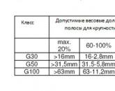
Popular
- Wood chips for boilers: characteristics, price and comparison with other heating materials Coal or wood pellets
- Cargo consolidation - European logistics company ELC
- Cargo consolidation - European logistics company ELC What is cargo consolidation in warehouses
- Principles of Flight Oxford Aviation Academy
- Calculation of the technological regime of overlay and vulcanization
- Basic guidance documents for construction, maintenance and other technical services for railway sidings
- Professional module program, maintenance and repair of road transport Monitoring and evaluation of development results
- Mobile application of Belarusbank - installation and connection
- Modern technologies for the production of rolled products and the formation of structure and properties
- What day of the week was your birthday?